|
|
1.Check the front impact sensor for dents, cracks, deformation or rust.
|
|
|
2.Check the connector for damage, and terminals for deformation.
|
|
|
3.Check the headlamp support panel for deformation.
|
|
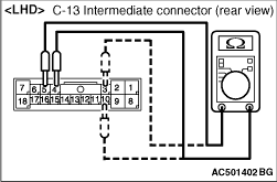
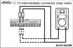
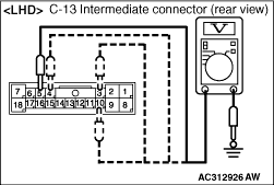
4.Measure the resistance of front impact sensor at the intermediate connector (the front
impact sensor is connected).
(1)
Disconnect intermediate connector C-13.
(2)
The resistance between the terminal 3 and 10, or between the terminal 4 and 5 on the
backside of intermediate connector (male side) <LHD>
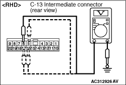
(3)
The resistance between the terminal 5 and 6, or between the terminal 16 and 17 on
the backside of intermediate connector (male side) <RHD>
|
|
| note |
Prior to that check, confirm the wiring harness between the front impact sensor and intermediate connector,
and repair if necessary.
|
|
Standard value: 820 ± 82 Ω
|
|
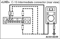
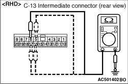
5.Measure the resistance of front impact sensor at the intermediate connector (the front
impact sensor is connected).
(1)
Disconnect intermediate connector C-13.
(2)
Continuity between the terminal 3, 4, 5 and 10 on the backside of intermediate connector
(male side) and body earth <LHD>
(3)
Continuity between the terminal 5, 6, 16 and 17 on the backside of intermediate connector
(male side) and body earth <RHD>
|
|
| note |
Prior to that check, confirm the wiring harness between the front impact sensor and intermediate connector,
and repair if necessary.
|
|
OK: Open circuit
|
|
6.Measure the voltage of front impact sensor at the intermediate connector (the front impact
sensor is connected).
(1)
Disconnect intermediate connector C-13.
(2)
Connect the negative battery cable.
(3)
Turn the ignition switch to "ON" position.
(4)
Voltage between the terminal 3, 4, 5 and 10 on the backside of intermediate connector
(male side) and body earth <LHD>
(5)
Voltage between the terminal 5, 6, 16 and 17 on the backside of intermediate connector
(male side) and body earth <RHD>
|
|
| note |
Prior to that check, confirm the wiring harness between the front impact sensor and intermediate connector,
and repair if necessary.
|
|
OK: 1 V or less
7.Check the headlamp support pane for deformation and rust.
|