|
|
(1)Disconnect the negative battery terminal.
|

|
(2)By sliding the A section (in the figure) of air bag module connector C-303 in the arrow
direction, disconnect the connector.
|

|
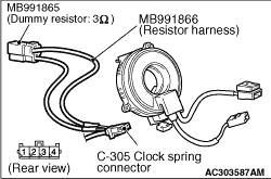
(3)Connect special tool dummy resistor (MB991865) to special tool resistor harness (MB991866).
(4)
| caution |
Do not insert a test probe into the
terminal from its front side directly as the connector contact pressure may be weakened.
|
Insert special tool (MB991866) into clock spring side air bag module connector C-303 by backprobing.
(5)Connect the negative battery terminal.
(6)Erase the diagnosis code memory, and check the diagnosis code.
Q.
Is diagnosis code B1401 set?
 Go to Step 2. Go to Step 2.
 Replace the driver’s air bag module (Refer to Replace the driver’s air bag module (Refer to  ). ).
|
|
|
(1)Disconnect the negative battery terminal.
|
|
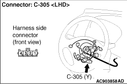
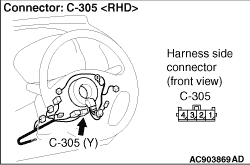
(2)Disconnect the clock spring connector C-305.
|
|
(3)Connect special tool dummy resistor (MB991865) to special tool resistor harness (MB991866).
(4)
| caution |
Do not insert a test probe into the
terminal from its front side directly as the connector contact pressure may be weakened.
|
Insert special tool (MB991866) into clock spring harness side connector C-305 (terminal
No.3 and 4) by backprobing.
(5)Connect the negative battery terminal.
(6)Erase the diagnosis code memory, and check the diagnosis code.
Q.
Is diagnosis code B1401 set?
Go to Step 3.
Replace the clock spring (Refer to ).
|
|
|
(1)Disconnect the negative battery terminal.
|
|
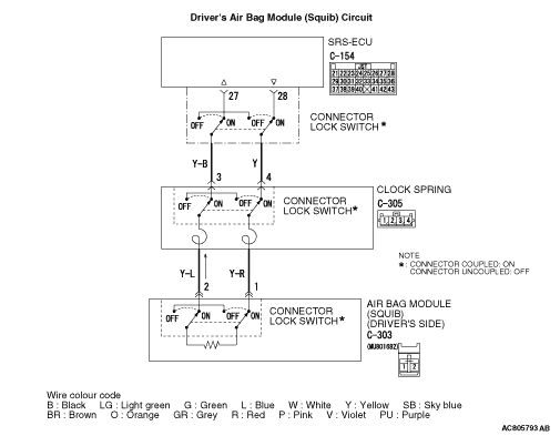
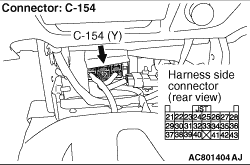
(2)Disconnect SRS-ECU connector C-154.
|
|
(3)
| danger |
To prevents the air bag from deploying unintentionally, disconnect the clock spring connector
C-305 to short the squib circuit.
|
Disconnect the clock spring connector C-305.
|
|
(4)
| caution |
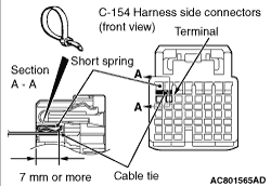
Insert an insulator such as a cable tie to a depth of 7 mm or more, otherwise the short
spring will not be released.
|
Insert a cable tie [3 mm wide, 0.5 mm thick] between terminals 27, 28
and the short spring to release the short spring.
|
|
(5)
| caution |
Do not insert a test probe into the terminal from its front side directly as the connector contact
pressure may be weakened.
|
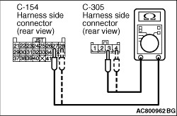
Resistance measurement between the following terminals.
- SRS-ECU connector C-154 terminal No.27 and the clock spring connector C-305 terminal
No.3
- SRS-ECU connector C-154 terminal No.28 and the clock spring connector C-305 terminal No.4
OK: Continuity (Less than 2 Ω)
Q.
Are the check results normal?
Go to Step 4.
Repair the harness wires between SRS-ECU connector C-154 (terminal No.27 and 28)
and clock spring connector C-305 (terminal No.3 and 4).
|
|
|
Q.
Is diagnosis code B1401 set?
|
|
|
Replace the SRS-ECU (Refer to ).
|
|
|
|
|
|
An intermittent malfunction is suspected (Refer to GROUP 00, How to Cope with
Intermittent Malfunction ).
|
|
|
|