|
|
(1)Disconnect the negative battery terminal.
|

|
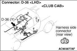
(2)Disconnect side-airbag module (RH) connector D-36. When disconnecting connector D-36,
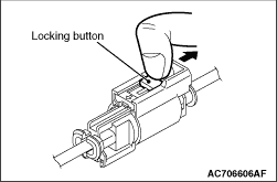
unlock the connector by sliding the locking button to the direction of the arrow as shown in
the figure, and then disconnect the connector.
|

|
(3)Connect special tool dummy resistor (MB991865) to special tool resistor harness (MB991866).
(4)
| caution |
Do not insert a test probe into the
terminal from its front side directly as the connector contact pressure may be weakened.
|
Insert special tool (MB991866) into the harness side connector D-36 by backprobing.
(5)Connect the negative battery terminal.
(6)Erase the diagnosis code memory, and check the diagnosis code.
Q.
Is diagnosis code B1422 set?
 Go to Step 2 Go to Step 2
 Replace the front seatback assembly (RH) (Refer to Replace the front seatback assembly (RH) (Refer to  ). ).
|
|
|
(1)Disconnect the negative battery terminal.
|

|
(2)Disconnect SRS-ECU connector C-155.
|
|
(3)
| danger |
To prevents the air bag from deploying unintentionally, disconnect
the side-airbag module (RH) connector D-36 to short the squib circuit.
|
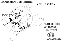
Disconnect side-airbag module (RH) connector D-36. When disconnecting connector D-36,
unlock the connector by sliding the locking button to the direction of the arrow as shown in
the figure, and then disconnect the connector.
|

|
(4)
| caution |
Insert an insulator such as a cable tie to a depth of 7 mm or more, otherwise the short
spring will not be released.
|
Insert a cable tie [3 mm wide, 0.5 mm thick] between terminals 53, 54
and the short spring to release the short spring.
|

|
(5)
| caution |
Do not insert a test probe into the terminal from its front side directly as the connector contact
pressure may be weakened.
|
Resistance measurement between C-155 harness side connector terminals 53, 54 and body
earth.
OK: Open circuit
Q.
Is the check result normal?
Go to Step 3
Repair the harness wires between SRS-ECU connector C-155 (terminal No.53 and 54)
and side-airbag module (RH) connector D-36 (terminal No.2 and 1).
|
|
|
Q.
Is diagnosis code B1422 set?
|
|
|
Replace the SRS-ECU (Refer to ).
|
|
|
|
|
|
An intermittent malfunction is suspected (Refer to GROUP 00, How to Cope with
Intermittent Malfunction ).
|
|
|
|
