|
|
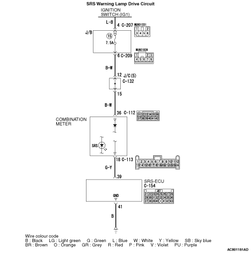
- Power for the SRS warning lamp is supplied from the ignition switch (IG1)
circuit.
- The SRS warning lamp illuminates when the ignition switch is turned to the "ON"
position and goes out after approximately 7 seconds if there is not a malfunction in the SRS
system.
|
|
|
This diagnosis code will be set if the SRS warning lamp driving circuit is short to earth.
|
|
|
- Damaged wiring harnesses of connectors
- Malfunction of the SRS-ECU
- Malfunction of the combination meter
|

|
Q.
Is the connector correctly engaged?
 Go to Step 2. Go to Step 2.
 Engage the connector correctly. Then go to Step 7. Engage the connector correctly. Then go to Step 7.
|
|
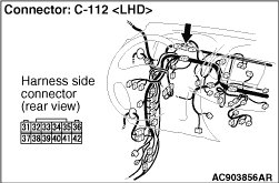
(1)Disconnect the combination meter connector C-112.
(2)Connect the negative battery terminal.
(3)Turn the ignition switch to the "ON" position.
(4)Measure the voltage between C-112 harness side connector terminal 36 and body earth.
OK: System voltage
Q.
Is the check result normal?
Go to Step 4.
Go to Step 3.
|
|
| note |
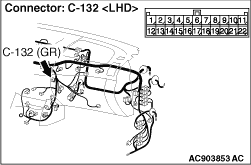
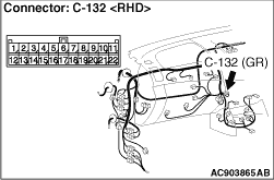
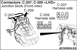
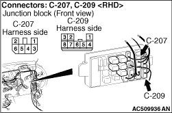
Prior to the wiring harness inspection, check junction block connector C-132, C-207 and
C-209, and repair if necessary.
|
Q.
Is the check result normal?
An intermittent malfunction is suspected (Refer to GROUP 00, How to Cope with
Intermittent Malfunction  ). ).
Repair the harness wires between ignition switch and the combination meter connector
C-112 (terminal No.36). Then go to Step 7.
|
|
Q.
Is the connector correctly engaged?
Go to Step 5.
Engage the connector correctly. Then go to Step 7.
|

|
Q.
Is the check result normal?
Go to Step 6.
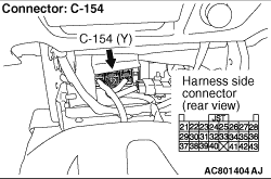
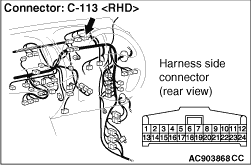
Repair the harness wires between the combination meter connector C-113 (terminal
No.18) and SRS-ECU connector C-154 (terminal No.39). Then go to Step 7.
|
|
|
(1)Disconnect the negative battery terminal.
|
|
(2)Disconnected the SRS-ECU connector C-154.
(3)Connect the negative battery terminal.
(4)Turn the ignition switch to the "ON" position.
Q.
Does the SRS warning lamp illuminate?
Go to Step 7.
Replace the combination meter (Refer to GROUP 54A, Combination Meter Assembly ).
Go to Step 7.
|
|
|
Check again if the diagnosis code is set.
|
|
|
(1)Erase the diagnosis code.
|
|
|
(2)Ignition: "LOCK" (OFF) position to "ON"
|
|
|
(3)On completion, check that the diagnosis code is not reset.
|
|
|
Q.
Is the diagnosis code set?
|
|
|
Replace the SRS-ECU (Refer to ).
|
|
|
|
|
|
An intermittent malfunction is suspected (Refer to GROUP 00, How to Cope with
Intermittent Malfunction ).
|
|
|
|