|
|
When the turn-signal lamp switch is operated, check that the turn-signal lamps illuminate/go
off normally.
|
|
|
Q.
Are the turn-signal lamps in good condition?
|
|
|
 First, repair the turn-signal lamps. Refer to trouble symptom chart First, repair the turn-signal lamps. Refer to trouble symptom chart  . .
|
|
|
|


|
Q.
Is the check result normal?
 Go to Step 3. Go to Step 3.
Repair the defective connector.
|
|
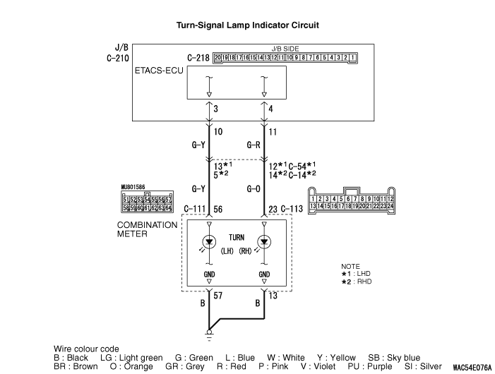
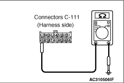
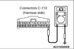
(1)Disconnect the connector, and measure at the wiring harness side.
|
|
(2)Resistance between C-111 combination meter connector terminal No.57 and body earth
OK: Continuity exists (2 Ω
or less)
|
|
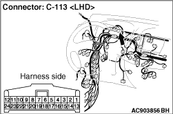
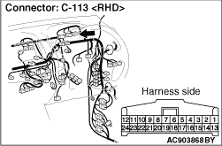
(3)Check the resistance between the C-113 combination meter connector terminal No.13 and
body earth.
OK: Continuity exists (2 Ω
or less)
Q.
Is the check result normal?
Go to Step 5.
Go to Step 4.
|
|
- Check the earth wires for open circuit.
Q.
Is the check result normal?
The trouble can be an intermittent malfunction (Refer to GROUP 00 -
How
to use Troubleshooting/inspection Service Points -
How to Cope with Intermittent
Malfunction ).
Repair the wiring harness.
|
|
Q.
Is the check result normal?
Go to Step 6.
Repair the defective connector.
|

|
| note |
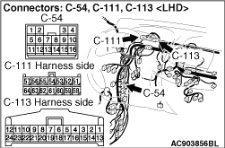
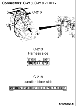
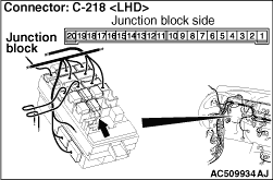
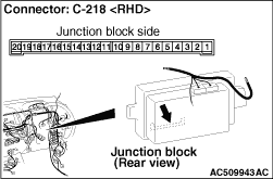
Prior to the wiring harness inspection, check junction block connector C-210 and intermediate
connector C-54 <LHD> or C-14 <RHD>, and repair if necessary.
|
- Check the output lines for open circuit.
Q.
Is the check result normal?
Go to Step 7.
Repair the wiring harness.
|
|
|
Check that the turn-signal lamp indicator illuminates normally.
|
|
|
Q.
Is the check result normal?
|
|
|
The trouble can be an intermittent malfunction (Refer to GROUP 00 -
How
to use Troubleshooting/inspection Service Points -
How to Cope with Intermittent
Malfunction ).
|
|
|
|
|
|
Replace the combination meter.
|
|
|
|