|
|
Use the M.U.T.-III to diagnose the CAN bus lines.
|
|
|
Q.
Is the check result normal?
|
|
|
 Repair the CAN bus line (Refer to GROUP 54C - Troubleshooting Repair the CAN bus line (Refer to GROUP 54C - Troubleshooting  ).
On completion, go to Step 5. ).
On completion, go to Step 5.
|
|
|
|
|
|
Check if the diagnosis code is set in either of the engine-ECU.
|
|
|
Q.
Is the diagnosis code set?
|
|
|
 Diagnose the engine-ECU (Refer to GROUP 13A - Troubleshooting .
On completion, go to Step 4. Diagnose the engine-ECU (Refer to GROUP 13A - Troubleshooting .
On completion, go to Step 4.
|
|
|
|
|
|
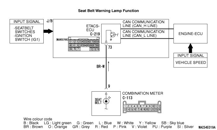
Check the input signals below, which are related to the seat belt warning lamp function.
|
|
|
- Turn the ignition switch to the "ON" position.
- Remove the each inserted seatbelt.
|
|
|
OK: Normal conditions are displayed for all the items.
|
|
|
Q.
Is the check result normal?
|
|
|
YES <All the signals are received normally.> : Go to Step 4. : Go to Step 4.
|
|
|
|
|
|
NO <The seat belt switch signal is not received.> : Refer to inspection procedure C-6 "The seat belt switch signal is not received <L.H.
drive vehicles> or <R.H. drive vehicles>."
|
|
|
|
|
|
NO <The ignition switch (IG1) signal is not received.> : Refer to inspection procedure C-3 "The ignition switch (IG1) signal is not received ."
|
|
|
|
|
|
Q.
Does the combination meter work?
|
|
|
Refer to symptom procedure 1 "Power supply circuit system check ."
|
|
|
|
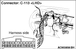
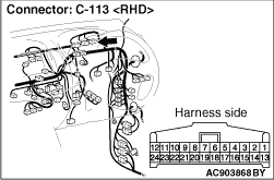

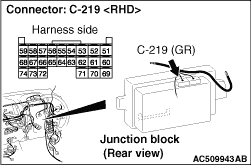
|
Q.
Is the check result normal?
Go to Step 6.
Repair the defective connector.
|
|
- Check the output lines for open circuit.
Q.
Is the check result normal?
Go to Step 7.
Repair the wiring harness.
|
|
|
The door-ajar warning lamp function should work normally.
|
|
|
Q.
Is the check result normal?
|
|
|
The trouble can be an intermittent malfunction (Refer to GROUP 00 - How
to use Troubleshooting/inspection Service Points - How to Cope with Intermittent
Malfunction ).
|
|
|
|
|
|
Replace the ETACS-ECU and register the ID codes (Refer to ).
|
|
|
|