|
|
Use the M.U.T.-III to diagnose the CAN bus lines.
|
|
|
Q.
Is the check result normal?
|
|
|
 Repair the CAN bus line (Refer to GROUP 54C - Troubleshooting Repair the CAN bus line (Refer to GROUP 54C - Troubleshooting  ).
On completion, go to Step 2. ).
On completion, go to Step 2.
|
|
|
|
|
|
Check if the diagnosis code is set.
|
|
|
Q.
Is the diagnosis code set?
|
|
|
Diagnose RV meter (Refer to RV meter, Troubleshooting ).
|
|
|
|
|
|
Check whether the ETACS-ECU diagnosis code is set.
|
|
|
Q.
Is the diagnosis code set?
|
|
|
 Diagnose ETACS-ECU (Refer to ETACS-ECU, Troubleshooting ).
After diagnosing the ETACS-ECU, go to Step 4. Diagnose ETACS-ECU (Refer to ETACS-ECU, Troubleshooting ).
After diagnosing the ETACS-ECU, go to Step 4.
|
|
|
|

|
Q.
Is the check result normal?
Go to Step 5
Repair the defective connector.
|
|
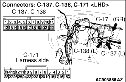
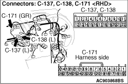
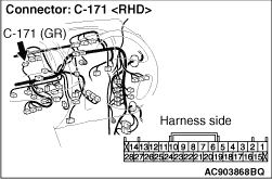
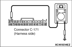
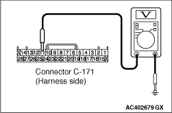
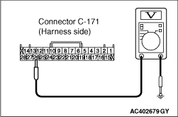
(1)Disconnect the connector, and measure at the wiring harness side.
|
|
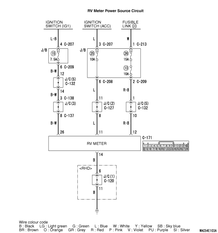
(2)Measure the resistance between C-171 RV meter connector terminal No.14 and body earth
OK: Continuity exists (2 Ω or less)
Q.
Is the check result normal?
Go to Step 7
Go to Step 6
|
|
- Check the earth wires for open circuit.
| note |
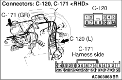
Prior to the wiring harness inspection, check joint connector C-120 <RHD>, and repair
if necessary.
|
Q.
Is the check result normal?
Retest the system.
Repair the wiring harness.
|
|
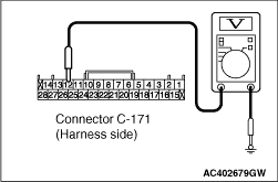
(1)Disconnect the connector, and measure at the wiring harness side.
(2)Ignition switch: LOCK (OFF) position
|
|
(3)Measure the voltage between C-171 RV meter connector terminal No.12 and body earth
OK: System voltage
Q.
Is the check result normal?
Go to Step 9
Go to Step 8
|
|
| note |
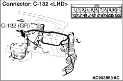
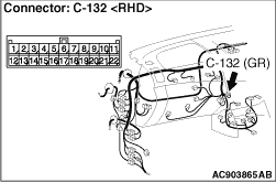
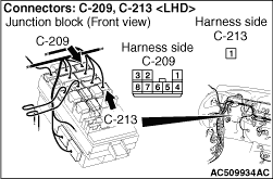
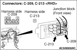
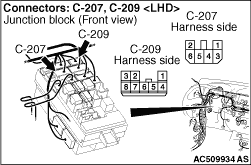
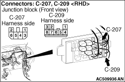
Prior to the wiring harness inspection, check joint connector C-132, junction block connectors
C-209 and C-213, and repair if necessary.
|
- Check the battery power supply open circuit and short circuit.
Q.
Is the check result normal?
Retest the system.
Repair the wiring harness.
|
|
(1)Disconnect the connector, and measure at the wiring harness side.
(2)Ignition switch: ACC
|
|
(3)Measure the voltage between C-171 RV meter connector terminal No.11 and body earth
OK: System voltage
Q.
Is the check result normal?
Go to Step 11
Go to Step 10
|
|
| note |
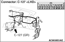
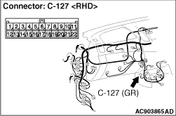
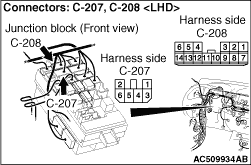
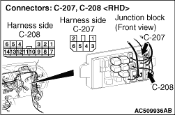
Prior to the wiring harness inspection, check joint connector C-127, junction block connectors
C-207 and C-208, and repair if necessary.
|
- Check the IG (ACC) power supply open circuit and short circuit.
Q.
Is the check result normal?
Refer to ignition switch ().
Retest the system.
|
|
(1)Disconnect the connector, and measure at the wiring harness side.
(2)Ignition switch: ON position
|
|
(3)Measure the voltage between C-171 RV meter connector terminal No.26 and body earth
OK: System voltage
Q.
Is the check result normal?
Go to Step 13
Go to Step 12
|
|
| note |
Prior to the wiring harness inspection, check joint connectors C-132, C-138 and C-137,
junction block connectors C-207 and C-209, and repair if necessary.
|
- Check the IG (IG1) power supply open circuit and short circuit.
Q.
Is the check result normal?
Refer to ignition switch ().
Retest the system.
|
|
|
Check that the RV meter shows the drive information when the RV meter is replaced temporarily.
|
|
|
Q.
Is the check result normal?
|
|
|
Check that the RV meter RV meter shows the drive information.
|
|
|
Q.
Is the check result normal?
|
|
|
The procedure is complete.
|
|
|
|