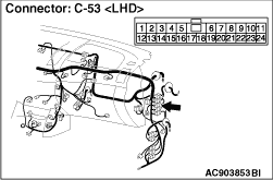

|
| caution |
The strand end of the twist wire should be within 10 cm from the connector. For details
refer to  . .
|
Q.
Is the check result normal?
 Go to Step 2. Go to Step 2.
 Repair the defective connector. Repair the defective connector.
|
|
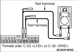
(1)Disconnect the connector, and measure at its female-side intermediate connector (at the
instrument panel wiring harness side).
(2)Turn the ignition switch to the LOCK (OFF) position.
(3)
| caution |
When measuring the resistance, disconnect the negative battery
terminal. For details refer to .
|
Ensure that the negative battery terminal is disconnected.
|
|
(4)Resistance between C-53 <LHD> or C-35 <RHD> intermediate connector terminal Nos.6
and 7
OK: 120 ± 20 Ω
Q.
Is the check result normal?
<Within 120 ± 20 Ω> Go to Step 3.
<Not within 120 ± 20 Ω> Go to Step 8.
|


|
| caution |
The strand end of the twist wire should be within 10 cm from the connector. For details
refer to .
|
|

|
When checking the joint connector, ensure that its wiring harness side and its short pins
are not damaged.
Q.
Is the check result normal?
Go to Step 4.
Repair a defective connector or replace the joint connector.
|
|
(1)Disconnect the connector, and measure at the wiring harness side.
(2)Turn the ignition switch to the LOCK (OFF) position.
(3)
| caution |
When measuring the resistance, disconnect the negative battery
terminal. For details refer to .
|
Ensure that the negative battery terminal is disconnected.
|


|
(4)Resistance between C-01 joint connector (CAN2) terminal Nos.9 and 20 <LHD>
OK: 120 ± 20 Ω
Resistance between C-01 joint connector (CAN2) terminal Nos.10 and 21 <RHD>
OK: 120 ± 20 Ω
| caution |
Strictly observe the specified wiring harness repair procedure.
For details refer to .
|
Q.
Is the check result normal?
YES <M/T> : <Within 120 ± 20 Ω> Repair the wiring harness
between joint connector (CAN2) and intermediate connector C-53 <LHD> or C-35 <RHD>.
YES <A/T> : <Within 120 ± 20 Ω> Go to Step 6. : <Within 120 ± 20 Ω> Go to Step 6.
NO : <Not within 120 ± 20 Ω> Go to Step 5.
|


|
(1)Remove the engine-ECU, and measure at the equipment side.
|

|
(2)Resistance between C-103 engine-ECU connector terminal Nos.108 and 109
OK: 120 ± 20 Ω
| caution |
Strictly observe the specified wiring harness repair procedure.
For details refer to .
|
Q.
Is the check result normal?
<Within 120 ± 20 Ω> Repair the wiring harness between
joint connector (CAN2) and the engine-ECU connector.
<Not within 120 ± 20 Ω> Check the engine-ECU connector,
and repair if necessary. If the engine-ECU connector is in good condition, replace the engine-ECU.
|
|
(1)Disconnect the connector, and measure at the wiring harness side.
(2)Turn the ignition switch to the LOCK (OFF) position.
(3)
| caution |
When measuring the resistance, disconnect the negative battery
terminal. For details refer to .
|
Ensure that the negative battery terminal is disconnected.
|
|
(4)Resistance between C-01 joint connector (CAN2) terminal Nos.10 and 21 <LHD>
OK: 1 kΩ or more
Resistance between C-01 joint connector (CAN2) terminal Nos.9 and 20 <RHD>
OK: 1 kΩ or more
| caution |
Strictly observe the specified wiring harness repair procedure.
For details refer to .
|
Q.
Is the check result normal?
<1 kΩ or more> Repair the wiring harness between joint
connector (CAN2) and intermediate connector C-53 <LHD> or C-35 <RHD>.
<Less than 1 kΩ> Go to Step 7.
|


|
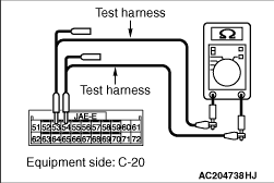
(1)Remove the A/T-ECU, and measure at the equipment side.
|
|
(2)Resistance between C-20 A/T-ECU connector terminal Nos.53 and 54
OK: 1 kΩ or more
| caution |
Strictly observe the specified wiring harness repair procedure.
For details refer to .
|
Q.
Is the check result normal?
<1 kΩ or more> Repair the wiring harness between joint
connector (CAN2) and the A/T-ECU connector.
<Less than 1 kΩ> Check the A/T-ECU connector,
and repair if necessary. If the A/T-ECU connector is in good condition, replace the
A/T-ECU.
|

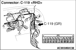
|
| caution |
The strand end of the twist wire should be within 10 cm from the connector. For details
refer to .
|
|
|
When checking the joint connector, ensure that its wiring harness side and its short pins
are not damaged.
Q.
Is the check result normal?
Go to Step 9.
Repair a defective connector or replace the joint connector.
|
|
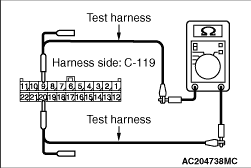
(1)Disconnect joint connector (CAN1), and measure at the wiring harness side.
(2)Turn the ignition switch to the LOCK (OFF) position.
(3)
| caution |
When measuring the resistance, disconnect the negative battery
terminal. For details refer to .
|
Ensure that the negative battery terminal is disconnected.
|
|
(4)Resistance between C-119 joint connector (CAN1) terminal Nos.9 and 20
OK: 120 ± 20 Ω
| caution |
Strictly observe the specified wiring harness repair procedure.
For details refer to .
|
Q.
Is the check result normal?
<Within 120 ± 20 Ω> Go to Step 11.
<Not within 120 ± 20 Ω> Go to Step 10.
|

|
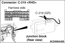
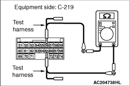
(1)Remove the ETACS-ECU, and measure at the equipment side.
|
|
(2)Resistance at C-219 ETACS-ECU connector terminal Nos.56 and 65
OK: 120 ± 20 Ω
Q.
Is the check result normal?
<Within 120 ± 20 Ω> Repair the wiring harness between
joint connector (CAN1) and the ETACS-ECU connector.
<Not within 120 ± 20 Ω> Check the ETACS-ECU connector,
and repair if necessary. If the ETACS-ECU connector is in good condition, replace the ETACS-ECU.
|
|
(1)Disconnect joint connector (CAN1), and measure at the wiring harness side.
(2)Turn the ignition switch to the LOCK (OFF) position.
(3)
| caution |
When measuring the resistance, disconnect the negative battery
terminal. For details refer to .
|
Ensure that the negative battery terminal is disconnected.
|

|
(4)Resistance between C-119 joint connector (CAN1) terminal Nos.7 and 18
OK: 1 kΩ or more
| caution |
Strictly observe the specified wiring harness repair procedure.
For details refer to .
|
Q.
Is the check result normal?
YES <vehicles without ABS, ASTC and A/C> : <1 kΩ or more> Go to Step 23.
YES <vehicles with ABS> : <1 kΩ or more> Go to Step 13.
YES <vehicles with ASTC> : <1 kΩ or more> Go to Step 15.
YES <vehicles without ABS and ASTC, and with A/C> : <1 kΩ or more> Go to Step 21.
NO : <Less than 1 kΩ> Go to Step 12.
|

|
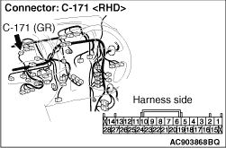
(1)Remove the RV meter, and measure at the equipment side.
|

|
(2)Resistance at C-171 RV meter connector terminal Nos.7 and 21
OK: 1 kΩ or more
Q.
Is the check result normal?
<1 kΩ or more> Repair the wiring harness between joint
connector (CAN1) and the RV meter connector.
<Less than 1 kΩ> Check the RV meter connector, and repair
if necessary. If the RV meter connector is in good condition, replace the RV meter.
|
|
(1)Disconnect joint connector (CAN1), and measure at the wiring harness side.
(2)Turn the ignition switch to the LOCK (OFF) position.
(3)
| caution |
When measuring the resistance, disconnect the negative battery
terminal. For details refer to .
|
Ensure that the negative battery terminal is disconnected.
|

|
(4)Resistance between C-119 joint connector (CAN1) terminal Nos.5 and 16
OK: 1 kΩ or more
| caution |
Strictly observe the specified wiring harness repair procedure.
For details refer to .
|
Q.
Is the check result normal?
YES <vehicles without A/C> : <1 kΩ or more> Go to Step 23.
YES <vehicles with A/C> : <1 kΩ or more> Go to Step 21.
NO : <Less than 1 kΩ> Go to Step 14.
|

|
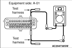
(1)Remove the ABS-ECU, and measure at the equipment side.
|
|
(2)Resistance at A-01 ABS-ECU connector terminal Nos.23 and 34.
OK: 1 kΩ or more
Q.
Is the check result normal?
<1 kΩ or more> Check intermediate connector C-13, and
repair if necessary. If the intermediate connector C-13 is in good condition, repair the wiring
harness between joint connector (CAN1) and the ABS-ECU connector.
<Less than 1 kΩ> Check the ABS-ECU connector, and repair
if necessary. If the ABS-ECU connector is in good condition, replace the hydraulic unit assembly.
|
|
(1)Disconnect joint connector (CAN1), and measure at the wiring harness side.
(2)Turn the ignition switch to the LOCK (OFF) position.
(3)
| caution |
When measuring the resistance, disconnect the negative battery
terminal. For details refer to .
|
Ensure that the negative battery terminal is disconnected.
|
|
(4)Resistance between C-119 joint connector (CAN1) terminal Nos.5 and 16
OK: 1 kΩ or more
| caution |
Strictly observe the specified wiring harness repair procedure.
For details refer to .
|
Q.
Is the check result normal?
<1 kΩ or more> Go to Step 17.
<Less than 1 kΩ> Go to Step 16.
|
|
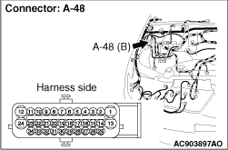
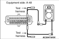
(1)Remove the ASTC-ECU, and measure at the equipment side.
|
|
(2)Resistance at A-48 ASTC-ECU connector terminal Nos.23 and 34
OK: 1 kΩ or more
Q.
Is the check result normal?
<1 kΩ or more> Check intermediate connector C-13, and
repair if necessary. If the intermediate connector C-13 is in good condition, repair the wiring
harness between joint connector (CAN1) and the ASTC-ECU connector.
<Less than 1 kΩ> Check the ASTC-ECU connector, and
repair if necessary. If the ASTC-ECU connector is in good condition, replace the hydraulic unit assembly.
|
|
(1)Disconnect joint connector (CAN1), and measure at the wiring harness side.
(2)Turn the ignition switch to the LOCK (OFF) position.
(3)
| caution |
When measuring the resistance, disconnect the negative battery
terminal. For details refer to .
|
Ensure that the negative battery terminal is disconnected.
|

|
(4)Resistance between C-119 joint connector (CAN1) terminal Nos.3 and 14
OK: 1 kΩ or more
| caution |
Strictly observe the specified wiring harness repair procedure.
For details refer to .
|
Q.
Is the check result normal?
<1 kΩ or more> Go to Step 19.
<Less than 1 kΩ> Go to Step 18.
|
|
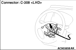
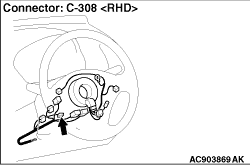
(1)Remove the steering wheel sensor, and measure at the equipment side.
|

|
(2)Resistance at C-308 steering wheel sensor connector terminal Nos.3 and 4
OK: 1 kΩ or more
Q.
Is the check result normal?
<1 kΩ or more> Repair the wiring harness between joint
connector (CAN1) and the steering wheel sensor connector.
<Less than 1 kΩ> Check the steering wheel sensor connector,
and repair if necessary. If the steering wheel sensor connector is in good condition, replace the
steering wheel sensor.
|
|
(1)Disconnect joint connector (CAN1), and measure at the wiring harness side.
(2)Turn the ignition switch to the LOCK (OFF) position.
(3)
| caution |
When measuring the resistance, disconnect the negative battery
terminal. For details refer to .
|
Ensure that the negative battery terminal is disconnected.
|

|
(4)Resistance between C-119 joint connector (CAN1) terminal Nos.4 and 15
OK: 1 kΩ or more
| caution |
Strictly observe the specified wiring harness repair procedure.
For details refer to .
|
Q.
Is the check result normal?
YES <vehicles without A/C> : <1 kΩ or more> Go to Step 23.
YES <vehicles with A/C> : <1 kΩ or more> Go to Step 21.
<Less than 1 kΩ> Go to Step 20.
|


|
(1)Remove the G and yaw rate sensor, and measure at the equipment side.
|

|
(2)Resistance at C-144 G and yaw rate sensor connector terminal Nos.2 and 3
OK: 1 kΩ or more
Q.
Is the check result normal?
<1 kΩ or more> Repair the wiring harness between joint
connector (CAN1) and the G and yaw rate sensor connector.
<Less than 1 kΩ> Check the G and yaw rate sensor connector,
and repair if necessary. If the G and yaw rate sensor connector is in good condition, replace the
G and yaw rate sensor.
|
|
(1)Disconnect joint connector (CAN1), and measure at the wiring harness side.
(2)Turn the ignition switch to the LOCK (OFF) position.
(3)
| caution |
When measuring the resistance, disconnect the negative battery
terminal. For details refer to .
|
Ensure that the negative battery terminal is disconnected.
|

|
(4)Resistance between C-119 joint connector (CAN1) terminal Nos.6 and 17
OK: 1 kΩ or more
| caution |
Strictly observe the specified wiring harness repair procedure.
For details refer to .
|
Q.
Is the check result normal?
<1 kΩ or more> Go to Step 23.
<Less than 1 kΩ> Go to Step 22.
|
|
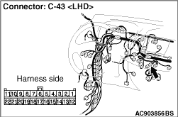
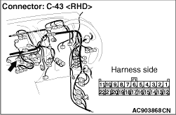
(1)Remove the A/C-ECU, and measure at the equipment side.
|

|
(2)Resistance at C-43 A/C-ECU connector terminal Nos.6 and 7
OK: 1 kΩ or more
Q.
Is the check result normal?
<1 kΩ or more> Repair the wiring harness between joint
connector (CAN1) and the A/C-ECU connector.
<Less than 1 kΩ> Check the A/C-ECU connector, and repair
if necessary. If the A/C-ECU connector is in good condition, replace the A/C-ECU.
|
|
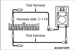
(1)Disconnect the joint connector (CAN1), and measure at the wiring harness side.
(2)Turn the ignition switch to the LOCK (OFF) position.
(3)
| caution |
When measuring the resistance, disconnect the negative battery
terminal. For details refer to .
|
Ensure that the negative battery terminal is disconnected.
|
|
(4)Resistance between C-119 joint connector (CAN1) terminal Nos.10 and 21
OK: 1 kΩ or more
| caution |
Strictly observe the specified wiring harness repair procedure.
For details refer to .
|
Q.
Is the check result normal?
<1 kΩ or more> Repair the wiring harness between joint
connector (CAN1) and the intermediate connector C-53.
<Less than 1 kΩ> Check the diagnosis connector, and
repair if necessary. If the diagnosis connector is in good condition, repair the wiring harness
between joint connector (CAN1) and the diagnosis connector.
|
