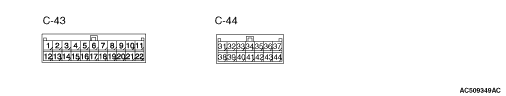
Terminal No.
|
Check items
|
Check conditions
|
Normal conditions
|
1
|
Air mix damper motor (COOL)
|
When the front air conditioner is moved to the COOL position
|
System voltage
|
When the front air conditioner is moved to the HOT position
|
0 - 1 V
|
2
|
Mode selection damper control motor (FACE)
|
When moving toward FACE position
|
System voltage
|
When moving toward DEF position
|
0 - 1 V
|
3
|
Outside/Inside air selection damper control
motor
|
When the damper is moved to the inside air recirculation position
|
1 V or less
|
When the damper is moved to the fresh air position
|
System voltage
|
4
|
Outside/Inside air selection damper control
motor
|
When the damper is moved to the inside air recirculation position
|
System voltage
|
When the damper is moved to the fresh air position
|
1 V or less
|
5
|
Output to the engine-ECU
|
A/C stopped
|
1 V or less
|
- A/C switch: ON
- Blower switch: ON
|
System voltage
|
6
|
Rear cooler switch (front) indicator
|
Rear cooler switch (front): ON
|
System voltage
|
Rear cooler switch (front): OFF
|
1.0 V or less
|
7
|
Input from diagnosis
|
Ignition switch: ON
|
Approximately 5 V
|
8
|
Battery power supply
|
Always
|
System voltage
|
10
|
Battery power supply
|
IG2: ON
|
System voltage
|
11
|
Communication with combination meter
|
-
|
-
|
12
|
Air mix damper motor (HOT)
|
When the front air conditioner is moved to the HOT position
|
System voltage
|
When the front air conditioner is moved to the COOL position
|
0 - 1 V
|
13
|
Mode selection damper control motor (DEF)
|
When moving toward DEF position
|
System voltage
|
When moving toward FACE position
|
0 - 1 V
|
14
|
Rear defogger relay
|
IG2: ON
|
System voltage
|
15
|
Rear cooler relay
|
IG2: ON
|
System voltage
|
16
|
Output to the engine-ECU (A/C2)
|
When the A/C is under low load
|
System voltage
|
When the A/C is under high load
|
1 V or less
|
18
|
Front blower relay
|
IG2: ON
|
System voltage
|
22
|
Earth
|
Always
|
1.0 V or less
|
32
|
Air mixing damper control motor and potentiometer input
|
MAX COOL position
|
Approximately 1
|
33
|
Mode selection damper control motor and potentiometer input
|
DEF position
|
0.5 - 0.8 V
|
34
|
Sensor power supply:
|
Ignition switch: IG2
|
5 V
|
35
|
Power transistor (DRAIN)
|
Air volume control dial: Maximum air volume (Preset temperature 18°C)
|
0 - 2 V
|
36
|
Power transistor (GATE)
|
Air volume control dial: Maximum air volume (Preset temperature 18°C)
|
System voltage
|
37
|
Tail lamp relay
|
Tail lamp: ON
|
System voltage
|
38
|
Sensor earth
|
Always
|
1 V or less
|
39
|
Air thermo sensor
|
Sensor probe temperature 25°C (1.5k Ω)
|
2.2 V
|
40
|
Interior temperature sensor
|
Sensor probe temperature: 25°C (4kΩ)
|
2.1 - 2.7 V
|
41
|
Photo sensor input
|
-
|
-
|
43
|
Rear cooler switch (front)
|
Rear cooler switch (front): ON
|
System voltage
|
Rear cooler switch (front): OFF
|
1 V or less
|
44
|
Earth
|
Always
|
1 V or less
|