EXTERIOR LAMPS
CONSTRUCTION DIAGRAM
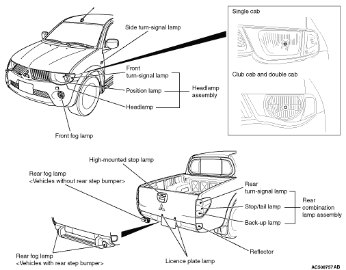
- Two large headlamp assemblies have been adopted each of which houses a front turn-signal lamp and a position lamp.
- Free curvature reflector has been installed at the headlamp assembly to improve distribution of lights and give crystal-image impression.
- The headlamp manual levelling system has been installed.
- The rear combination lamp assembly integrates the tail lamp, stop lamp, rear turn-signal lamp, and back-up lamp.
- Free curvature reflector has been installed at the rear combination lamp assembly, giving the crystal-image impression.
- High-mounted stop lamp has been installed at the rear gate outside handle garnish to achieve a sense of unity with an outside handle.
- For the high-mounted stop lamp, clear-taste cutting lens has been installed to achieve a sense of unity with a rear combination lamp assembly.
- Reflector has been embedded in the vehicle body panel to achieve a sense of unity with the body shape.
- The front fog lamp has been installed. <Club cab and double cab>
- The rear fog lamp has been installed to the driver’s side. <Vehicles without rear step bumper>
- The rear fog lamp has been installed to each side of the rear step bumper. <Vehicles with rear step bumper>
- The lighting system is provided with headlamp automatic-shutdown function, daytime running lamp function and comfort flashing function (Refer to Function and control by ECUs
 ).
).
SPECIFICATIONS
| Item |
Specification |
||
| Headlamp assembly |
High-beam/low-beam W/W |
60/55 (H4) |
|
| Position lamp W |
5 (W5W) |
||
| Front turn-signal lamp W |
21 (PY21W) |
||
| Side turn-signal lamp W |
5 (W5W) |
||
| Rear combination lamp assembly W |
Stop/tail lamp W/W |
21/5 (P21/5W) |
|
| Rear turn-signal lamp W |
16 (W16W) |
||
| Back-up lamp W |
16 (W16W) |
||
| High-mounted stop lamp W × quantity |
5 ×4(W5W) |
||
| Licence plate lamp W |
5 (W5W) |
||
| Front fog lamp W |
55 (H11) |
||
| Rear fog lamp W |
Vehicles without rear step bumper |
21 (P21W) |
|
| Vehicles with rear step bumper |
21 (W21W) |
||
| note | The brackets ( ) show the bulb type. |
HEADLAMP LEVELLING SYSTEM |
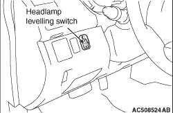 |
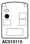
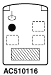
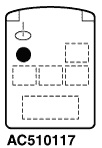
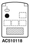
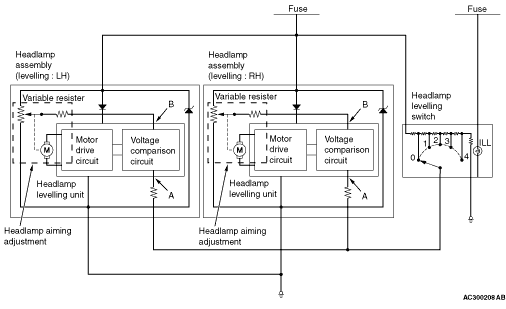
The beam direction of the headlamps changes according to the number of passengers and the amount of load. The headlamp levelling function is a system that allows the driver to change the direction of headlamp beam so that the drivers of oncoming cars are not dazzled by the headlamps. The headlamp levelling switch allows changing the direction in five steps: 0 to 4. |
RELATIONSHIP BETWEEN THE SWITCH POSITIONS AND THE NUMBER OF PASSENGERS/LOADS
| Cabin style |
Single cab |
Club cab |
Double cab |
|||
| Passenger and load |
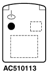 |
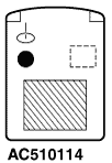 |
 |
 |
 |
 |
| Driver only |
Driver and full luggage loading |
Driver only |
Driver and full luggage loading |
Driver only |
Driver and full luggage loading |
|
| Switch position |
0 |
2 |
0 |
2*1 or 3*2 |
0 |
2*3 or 3*4 |
|
OPERATION
1.
2.
3.