|
|
1.Remove all ignition coils.
|
|
|
2.Remove the cylinder head cover.
| caution |
Turn the crankshaft always clockwise.
|
|
|
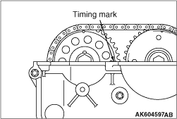
3.Turn the crankshaft clockwise, and align the timing mark on the exhaust camshaft sprocket against the upper face of the cylinder head as shown in Figure. Therefore, No.1 cylinder goes to the compression top dead centre.
|
|
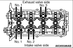
4.Using a thickness gauge, measure the valve clearance with the arrow shown in Figure. If deviated from the standard value, make note for the valve clearance.
Standard value:
Intake valve 0.22 ± 0.04 mm
Exhaust valve 0.30 ± 0.04 mm
|
|
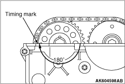
5.Turn the crankshaft clockwise 360 degrees, and put the timing mark on the exhaust camshaft sprocket in position shown in Figure. Therefore, No.4 cylinder goes to the compression top dead centre.
|
|
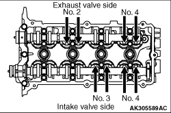
6.Check the valve clearance with the arrow shown in Figure. In the same procedure as 4.
7.If the valve clearance is deviated from the standard value, remove the camshaft and the valve tappet. For the camshaft removal, refer to  GROUP 11A - Camshaft Removal and Installation. GROUP 11A - Camshaft Removal and Installation.
|
|
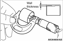
8.Using a micrometer, measure the thickness of the removed valve tappet.
|
|
9.Calculate the thickness of the newly installed valve tappet through the following equation.
A: thickness of newly installed valve tappet
B: thickness of removed valve tappet
C: measured valve clearance
Equation
Intake valve: A = B + (C - 0.22 mm)
Exhaust valve: A = B + (C - 0.30 mm)
| note |
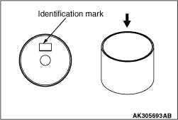
The valve tappet ranges 2.70 - 3.30 mm and has 31 types per 0.02 mm. The thickness below a decimal point is stamped on the reverse side of the valve tappet.
Example: In case of 2.90 mm, "90" is stamped.
|
10.Install the valve tappet selected through the procedure 10, and put the camshaft in position. For the camshaft installation, refer to GROUP 11A - Camshaft Removal and Installation.
11.After installing the camshaft, measure the value clearance using procedure 3 to 6. Confirm the clearance is within the standard value.
| caution |
Completely remove all the old liquid gasket, which might be remaining among the components.
|
|
|
12.Remove any liquid gasket remaining on the cylinder head cover, the timing chain case and the cylinder head.
| caution |
The cylinder head cover should be installed within 3 minutes of applying liquid gasket.
|
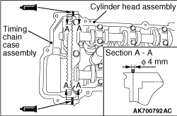
13.Apply a 4 mm bead of liquid gasket as illustrated.
Specified sealant:
Three bond 1217G or equivalent
|
|
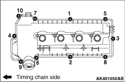
14.In accordance with the procedure shown in figure, tighten the bolt of the cylinder head cover to 9.0 ± 1.0 N·m.
15.Install the ignition coils.
|