
|
| note |
- Mark direction of rotation before removing.
- Check for wear.
- Do not kink.
- To tension and release timing belt, use special tool Pin wrench (MB995207). The tensioner
has an additional hexagon hole as shown in the illustration. This does not alter the procedure.
- Adjustment work on timing belts must be performed only on cold engines, as the indicator
on the tensioning element changes depending on the engine temperature.
|
1.Remove upper guard for timing belt.
2.Remove belt pulley vibration damper.
3.Remove lower and centre guards for timing belt.
4.Turn crankshaft to TDC No. 1 cylinder.
| note |
Gradual introduction of oval crankshaft belt pulleys. When installing this belt pulley,
the special tool crankshaft stoper (MB995231) must be installed to determine the TDC position.
|
|

|
5.Oval belt pulley, lock using special tool crankshaft stoper (MB995231), TDC marking at
1 o’clock.
|
|
6.
| note |
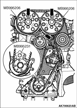
Turn crankshaft until marking on crankshaft pulley and tooth segments of camshaft sprockets
are on top. Marking on timing belt guard must align with camshaft sender wheel as shown in the
illustration.
|
Lock crankshaft sprocket with special tool Crankshaft stopper (MB995231).
7.To do this, push crankshaft stop into teeth of timing belt pulley from its face side.
| note |
- The marks on the crankshaft sprocket and the crankshaft stop must align.
- At the same time, the pin of the crankshaft stop must engage in the drilling in
the front case.
- The engine bracket must be loosened only when the assembly mounting has been removed.
|
8.Mark direction of rotation of timing belt.
|
|
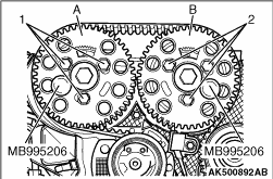
9.Loosen camshaft sprocket securing bolts "1" and "2" until camshaft sprockets can be turned
in elongated holes.
10.Lock hubs using special tool Sprocket locking pin (MB995206). To do this, slide locking
pins through outer free elongated holes into holes in cylinder head.
11.Loosen tensioning roller securing nut.
|

|
12.Turn special tool Pin wrench (MB995207) anti-clockwise until timing belt tensioning roller
can be locked with special tool Locking pin (MB995208).
|

|
13.Turn special tool Pin wrench (MB995207) clockwise to stop and tighten securing nut "1"
hand tight.
14.Remove engine bracket downwards.
15.Remove timing belt first from water pump and then from remaining pulleys.
|

|
Remove securing bolts for water pump and carefully remove water pump.
| note |
Always renew seals and gaskets.
|
|

|
Remove crankshaft sprocket. To do this, lock timing belt pulley using special tool Crankshaft
sprocket stopper (MB995201).
| note |
When bolting on counter-hold, place two washers between timing belt pulley and counter-hold.
|
|
|
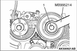
1.Using special tool Sprocket holder (MB995214), loosen hub securing bolt "1."
2.Loosen hub securing bolt about 2 turns.
|
|
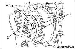
3.Fit special tool Sprocket puller (MB995215) and align it with holes in hub.
4.Tighten securing bolts "1."
5.Apply tension to hub by evenly tightening puller "2" until hub separates from taper
of camshaft.
| note |
When doing this, hold puller with 30 mm spanner.
|
6.Remove hub from taper of camshaft.
|
|
2.Using special tool Sprocket holder (MB995214), tighten securing bolts "1" for hubs to
the specified torque of 100 N·m.
|

|
3.Push camshaft sprockets onto hubs.
| note |
The toothed segment of the camshaft sprocket must be on top as shown in the illustration.
|
4.Hand tighten securing bolts "1" and "2" on camshaft sprockets so that there is no
play.
|
|
5.Lock hubs using special tool Sprocket locking pin (MB995206).
|

|
1.Wipe dirt on the crankshaft sprocket hole using a rag.
2.Using a rag, wipe dirt on the crankshaft sprocket installation surface. And then perform
degreasing.
| note |
Degreasing is necessary to prevent decrease in friction between the mating surface due
to presence of oil.
|
|
|
1.Moisten new O-ring with coolant.
2.Insert water pump in cylinder block and tighten securing bolts to the specified torque
of 15 N·m.
| note |
The water pump plug faces downwards.
|
|
|
|
1.Tensioning roller must be locked with special tool Tensioner locking pin (MB995208)
and secured to right stop.
|
|
|
2.Camshafts are locked using special tool Sprocket locking pin (MB995206).
|
|
|
3.Crankshaft is locked using special tool Crankshaft stopper (MB995231).
|
|
|
4.Rotated camshaft sprockets in their elongated holes clockwise to stop.
|
|
|
5.Fit timing belt to crankshaft pulley, tensioning roller and camshaft sprocket and
idler roller.
|
|
|
6.Then fit timing belt on water pump timing belt pulley.
|
|
|
7.Install engine bracket from below and insert lower securing bolt.
|
|
|
8.Loosen tensioning roller securing nut and pull out special tool Tensioner rocking
pin (MB995208).
|


|
9.
| note |
Ensure that tensioning roller seats correctly in rear timing belt guard as shown in the
illustration.
|
Now carefully turn tensioning roller clockwise using special tool Pin wrench (MB995207)
until indicator is in middle of gap in base plate as shown in the illustration.
10.Ensure that securing nut does not turn as well.
11.Hold tensioning roller in this position and tighten tensioning roller securing nut
as follows: 20 N·m and 45° (1/8 turn) further.
| note |
When securing nut is tightened, indicator will turn maximum 5 mm to right out of base
plate notch. This setting must not be corrected because the timing belt will settle after it
has run a while.
|
|
|
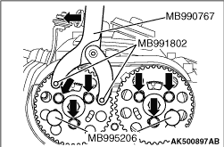
12.Apply special tools FR hub & end yoke holder (MB990767) and Pin B (MB991802)
as shown in the illustration. Press them in direction of arrow keeping camshaft sprocket under tension.
13.In this position, tighten camshaft sprocket securing bolts to the specified torque
of 25 N·m as shown in the illustration.
14.Remove special tools Sprocket locking pin (MB995206) and Crankshaft stopper (MB995231).
15.Turn crankshaft two rotations in engine direction of rotation and set again to TDC
No. 1 cylinder.
|
|
16.Lock hub "A" by turning in engine direction of rotation until special tool Sprocket locking
pin (MB995206) engages while turning.
17.Check whether:
- Hub "B" can be locked using special tool Sprocket locking pin (MB995206).
- Crankshaft can be locked using special tool Crankshaft stopper (MB995231).
- Tensioning roller indicator is centred or maximum 5 mm to right of base plate notch.
18.If the hub "B" cannot be locked:
Loosen camshaft sprocket "A" securing bolts "1."
| note |
Hub "A" must be locked using special tool Sprocket locking pin (MB995206).
|
|
|
19.Turn crankshaft until hub of camshaft sprocket "B" can be locked using special tool Sprocket
locking pin (MB995206). Loosen camshaft sprocket "B" securing bolts "2."
|
|
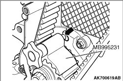
20.Turn crankshaft slightly against engine direction of rotation until the pin of the crankshaft
stop is positioned just before the hole in the front case as shown in the illustration.
21.Now turn crankshaft in engine direction of rotation until crankshaft stop pin engages
in front case whilst turning.
|
|
22.Apply special tools FR hub & yoke holder (MB990767) and Pin B (MB991802) as shown
in the illustration. Press them in direction of arrow keeping camshaft sprocket under tension.
23.In this position, tighten camshaft sprocket securing bolts as shown in the illustration.
24.Remove special tools Sprocket locking pin (MB995206) and Crankshaft stopper (MB995231).
25.Turn crankshaft two rotations in engine direction of rotation and set again to TDC
No. 1 cylinder.
26.Repeat check.
27.Install centre and lower timing belt guard.
|

