
|
While compressing the valve spring using the special tool Valve spring compressor (MD999597),
remove the retainer lock.
| note |
To facilitate reassembly, the valve, spring and other parts removed should be kept together
and attached with a tag showing where it has been assembled including the cylinder number.
|
|
|
1.Install the valve spring seat.
2.
| caution |
- The
valve stem seal should not be reused.
- A new valve stem seal should be installed correctly using the special
tool. Incorrectly installed valve stem seal will allow engine oil to leak through into the combustion
chamber.
|
Lightly coat a new valve stem seal with engine oil.
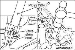
3.Insert the new valve stem seal into the valve guide using the special tool Valve stem
seal installer (MB991994).
| note |
Use the special tool, on which the number "MB991994A" is stamped.
|
|
|
While compressing the valve spring using the special tool Valve spring compressor (MD999597),
install the retainer lock.
|
|
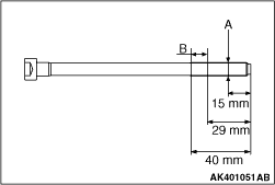
1.Inspect all reused cylinder bolts according to the following procedure.
(1)
Measure the outside diameter shown in the illustration (arrow "A").
(2)
Measure the smaller outside diameter shown in the illustration (arrow "B").
(3)
When the difference between the smaller outside diameters (arrow "A" and "B") exceeds
the standard value, replace the cylinder head bolt.
Standard value: 0 - 0.15 mm
2.Install the cylinder head bolt and washer assembly onto the cylinder head.
|

|
3.In accordance with the installation order, tighten them to the specified torque of 24.5 ± 2
N·m in several steps.
4.Make sure all bolts reach the specified torque.
|

|
5.Put paint marks on the bolt heads and the cylinder as illustrated.
6.
| caution |
- When the tightening
angle is smaller than the specified tightening angle, the appropriate tightening capacity cannot
be secured.
- When the tightening angle is larger than the specified tightening angle, remove
the bolt to start from the beginning again according to the procedure.
|
Tighten the bolts in the correct sequence by 180 to 184 degree angle.
Ensure that the paint marks on the bolt heads and the cylinder are aligned in a straight
line.
|

