REMOVAL AND INSTALLATION
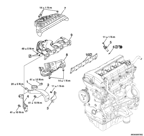


Removal steps

>>A<<
1.
Exhaust manifold bracket D

>>A<<
2.
Exhaust manifold bracket B


3.
Crank angle sensor cover

>>A<<
4.
Exhaust manifold bracket A

>>B<<
5.
Crank angle sensor

>>B<<
6.
O-ring


7.
Exhaust manifold upper cover


8.
Exhaust manifold lower cover


9.
Exhaust manifold


10.
Exhaust manifold gasket

INSTALLATION SERVICE POINTS


>>A<< EXHAUST MANIFOLD BRACKET INSTALLATION


caution The exhaust manifold gasket, washers and nuts must not be reused.


1.Make sure that exhaust manifold bracket B is in intimate contact with the exhaust manifold and exhaust manifold bracket A, and then tighten it to the specified torque.

    M10 × 30: 41 ± 10 N·m

    M8 × 20: 20 ± 5 N·m

>>B<< CRANK ANGLE SENSOR / O-RING INSTALLATION


caution
  • Do not apply a force such as torsion or twist to the O-ring during assembly of the sensor.
  • Assemble the sensor, taking care not to give a shock to it.
  • Do not use a sensor that has fallen down.
Tighten the crank angle sensor to the specified torque of 11 ± 1 N·m.