|
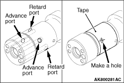
1.Seal with a tape all the intake camshaft ports for the advanced angle and the retarded
angle.
2.Make a hole on the port for the advanced angle.
|
|
| caution |
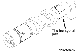
Fix the camshaft on a vise not to damage it.
|
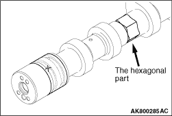
3.Fixing the hexagonal area of the intake camshaft on a vise, install the intake V.V.T. sprocket.
|
|
| caution |
When applying air pressure, keep in mind that oil could splash.
|
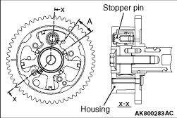
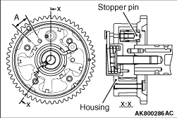
4.By applying air pressure slowly to the holed port for the advanced angle, remove the
stopper pin.
5.Turn the intake V.V.T. sprocket housing in the right and left directions. Check it
smoothly moves in the range of A (approximately 12.5°)
| note |
The stopper pin is locked in the most retarded angle position.
|
6..After the check, remove the intake V.V.T. sprocket from the intake camshaft
7.Completely remove the tape sealing the intake camshaft ports for the advanced angle
and for the retarded angle.
|
|
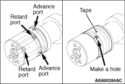
1.Seal with a tape all the exhaust camshaft ports for the advanced angle and the retarded
angle.
2.Make a hole on the port for the retarded angle.
|
|
| caution |
Fix the camshaft on a vise not to damage it.
|
3.Fixing the hexagonal area of the exhaust camshaft on a vise, install the exhaust V.V.T. sprocket.
|
|
| caution |
When applying air pressure, keep in mind that oil could splash.
|
4.By applying air pressure slowly to the holed port for the retarded angle, remove the
stopper pin.
5.Turn the exhaust V.V.T. sprocket housing in the right and left directions. Check it
smoothly moves in the range of A (approximately 10°)
| note |
The stopper pin is locked in the most advanced angle position.
|
6..After the check, remove the exhaust V.V.T. sprocket from the exhaust camshaft
7.Completely remove the tape sealing the exhaust camshaft ports for the advanced angle
and for the retarded angle.
|
|
|
Measure valve clearance in the following procedure.
|
|
|
Check and adjust the valve clearance with the timing chain installed.
|
|
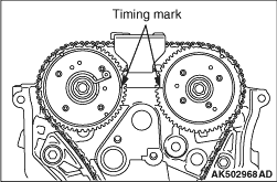
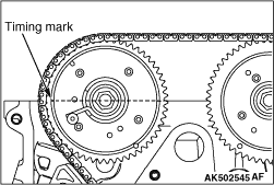
1.Rotate the crankshaft clockwise to align the timing mark of the V.V.T. sprocket with the
top surface of the cylinder head as illustrated. (Set the No. 1 piston at top dead centre on
the compression stroke.)
|

|
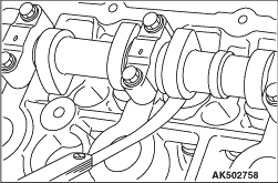
2.Valve clearance can be measured at the illustrated location in this condition.
|
|
3.Use a free gauge to measure clearance between the camshaft and valve tappet.
Standard value (cold engine)
Intake side: 0.20 ±
0.03 mm
Exhaust side: 0.30 ±
0.03 mm
4.If measured values are out of the standard value, record measured values.
|
|
5.Rotate the crankshaft by one turn clockwise to set the No. 4 piston at top dead centre
on the compression stroke.
| note |
The timing mark of the V.V.T. exhaust sprocket must be at the illustrated position.
|
|

|
6.Valve clearance can be measured at the illustrated location in this condition.
7.If measured values are out of the standard value, record measured values.
8.If the measured value is out of the standard value, replace the valve tappet.
| note |
There are 47 kinds of valve tappets at intervals of 0.015 mm in the range between 3.000 and
3.690 mm.
|
|
|
9.Select a valve tappet in the following procedure.
(1)
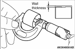
Measure thickness of a removed valve tappet.
(2)
Calculate thickness of a valve tappet so that valve clearance meets the standard value.
A: Thickness of valve tappet to be selected
B: Thickness of removed valve tappet
C: Measured valve clearance
Formula
Intake side: A =
B +
(C -
0.20 mm)
Exhaust side: A =
B +
(C -
0.30 mm)
Refer to "Removal and installation of camshaft" for removal, installation and inspection
procedure of valve tappets.
|