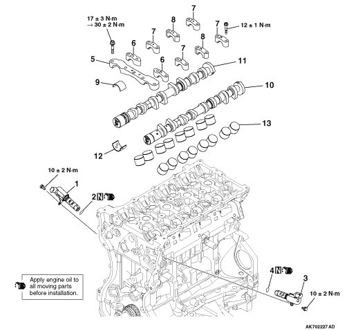
|
| caution |
Loosing the installation bolts for the camshaft bearing cap at
the same time causes the valve spring force, which makes the installation bolts jump out, resulting
in the damaged threads. Always loose them four or five times.
|
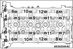
First remove a mounting bolt of the front camshaft bearing cap and then
a mounting bolt of each camshaft bearing cap in the order shown in the illustration.
|
|
|
Pick out valve tappets with fingers and store removed valve tappets with
tags describing the installed position attached for reassembly.
|
|
|
Install valve tappets at the same position based on tags describing the
installed position for reassembly.
|
|
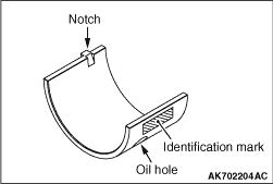
1.When replacing a camshaft bearing, select a bearing with the size corresponding to the
identification mark in the table below.
2.Install camshaft bearings on the cylinder head.
|
|
Front camshaft bearing cap
|
Camshaft bearing
|
Identification mark
|
Inner diameter mm
|
Identification mark
|
1
|
40.000 -
40.008
|
1
|
2
|
40.008 -
40.016
|
2
|
3
|
40.016 -
40.024
|
3
|
|
|
|
3.The identification mark of the camshaft bearing is stamped at the illustrated position.
|
|
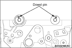
4.Set the dowel pins of the camshaft at the illustrated positions.
|
|
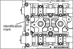
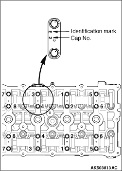
5.Install them upon checking the identification mark so as not to misidentify cap No. and
to confuse the intake side with the exhaust side.
Identification mark
I: Intake side
E: Exhaust side
6.Tighten each camshaft bearing cap mounting bolt to the specified torque of 12 ±
1
N·m in the order of number shown in the figure in two or three steps.
|

|
7.Tighten each front camshaft bearing cap mounting bolt to the temporarily torque of 17 ±
3
N·m in the order of number shown (1).
8.Tighten each front camshaft bearing cap mounting bolt to the specified torque of 30 ±
2
N·m in the order of number shown (2).
|
|
1.
| caution |
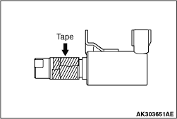
- The O-ring must not be reused.
- Wind non-adhesive tape (seal tape, etc.) around the notch of the oil passage of
the oil feeder control valve before installing the O-ring to prevent damage. Damage to the O-ring
causes oil leakage.
|
Apply a small amount of engine oil to the O-ring of the oil feeder control
valve.
2.Install the oil feeder control valve on the cylinder head.
3.Tighten the oil feeder control valve to the specified torque of 10 ±
2 N·m.
|