|
|
The output signals of the sensors and the conditions of the actuation signals of the actuators
can be inspected visually by observing the waveforms on the oscilloscope.
|
|
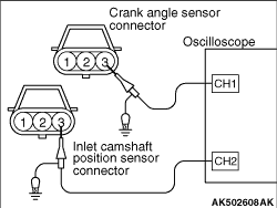
1.Disconnect the inlet camshaft position sensor connector and insert the special tool test
harness (MB991709) in-between the separated connectors. (Always mate all the terminals.)
2.Disconnect the crank angle sensor connector and insert the special tool test harness
(MB991709) in-between the separated connectors. (Always mate all the terminals.)
3.Connect the probe of each channel of the oscilloscope to terminal No. 3 of the inlet
camshaft position sensor connector and terminal No. 3 of the crank angle sensor connector, respectively.
|
|
|
1.Disconnect the engine-ECU connector and connect the special tool Power plant ECU check
harness (MB992110) in between.
|
|
|
2.Connect the oscilloscope special patterns pickup to engine-ECU terminal No. 14 (When
checking the inlet camshaft position sensor signal wave pattern).
|
|
|
3.Connect the oscilloscope special patterns pickup to engine-ECU terminal No. 8 (When
checking the crank angle sensor signal wave pattern).
|
|
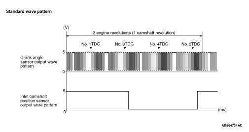
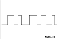
Wave pattern characteristics
Rectangular wave will be outputted while the engine
is not started.
|
|
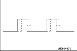
Wave pattern characteristics
Wave pattern is displaced in the forward or backward direction.
Cause of problem
Loose timing chain
Abnormal sensing section
|
|
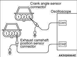
1.Disconnect the exhaust camshaft position sensor connector and insert the special tool
test harness (MB991709) in-between the separated connectors. (Always mate all the terminals.)
2.Disconnect the crank angle sensor connector and insert the special tool test harness
(MB991709) in-between the separated connectors. (Always mate all the terminals.)
3.Connect the probe of each channel of the oscilloscope to terminal No. 3 of the exhaust
camshaft position sensor connector and terminal No. 3 of the crank angle sensor connector, respectively.
|
|
|
1.Disconnect the engine-ECU connector and connect the special tool Power plant ECU check
harness (MB992110) in between.
|
|
|
2.Connect the oscilloscope special patterns pickup to engine-ECU terminal No. 7 (When
checking the exhaust camshaft position sensor signal wave pattern).
|
|
|
3.Connect the oscilloscope special patterns pickup to engine-ECU terminal No. 8 (When
checking the crank angle sensor signal wave pattern).
|
|
|
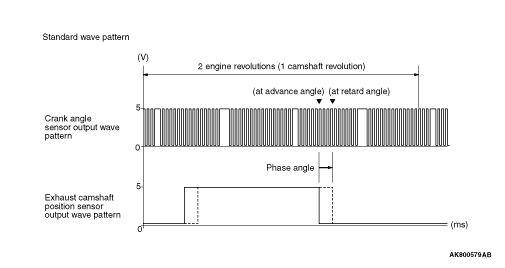
- Verify that the relative position of the exhaust camshaft position sensor’s
output wave changes when the low load operation changes to the high load operation.
|
|
Wave pattern characteristics
Rectangular wave will be outputted while the engine
is not started.
|
|
Wave pattern characteristics
Wave pattern is displaced in the forward or backward direction.
Cause of problem
Loose timing chain
Abnormal sensing section
|
|
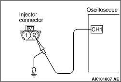
1.Disconnect the injector connector and insert the special tool Test harness (MB991658)
in-between the separated connectors. (Always mate all the terminals.)
2.Connect the oscilloscope probe to terminal No. 2 of the injector connector.
|
|
|
1.Disconnect the engine-ECU connector and connect the special tool Power plant ECU check
harness (MB992110) in between.
|
|
|
2.Connect the oscilloscope special patterns pickup to engine-ECU terminal No. 2 (When
checking the No. 1 cylinder).
|
|
|
3.Connect the oscilloscope special patterns pickup to engine-ECU terminal No. 3 (When
checking the No. 2 cylinder).
|
|
|
4.Connect the oscilloscope special patterns pickup to engine-ECU terminal No. 18 (When
checking the No. 3 cylinder).
|
|
|
5.Connect the oscilloscope special patterns pickup to engine-ECU terminal No. 19 (When
checking the No. 4 cylinder).
|
|
|
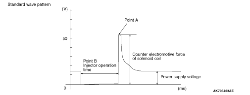
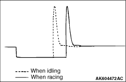
- Point A: The level of counter electromotive force of solenoid coil:
|
|
- Point B: Injector operation time
Operation time
|
Consistent with the displayed time on M.U.T.-III.
|
Force an excessive acceleration.
|
The drive period will once extend greatly, then will be settled to that
corresponding to the engine speed.
|
|
|
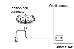
1.Disconnect the ignition coil connector and insert the special tool test harness (MB991658)
in-between the separated connectors. (Always mate all the terminals.)
2.Connect the oscilloscope probe to terminal No. 2 of the ignition coil connector.
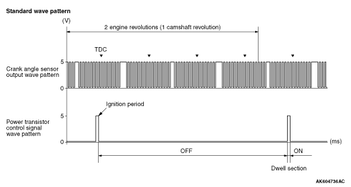
3.To verify the ignition advance angle, observe it simultaneously with the crank angle
sensor output signals.
|
|
|
1.Disconnect the engine-ECU connector and connect the special tool Power plant ECU check
harness (MB992110) in between.
|
|
|
2.Connect the oscilloscope probe to engine-ECU terminal No. 4. (When checking the No.
1 cylinder.)
|
|
|
3.Connect the oscilloscope probe to engine-ECU terminal No. 5. (When checking the No.
2 cylinder.)
|
|
|
4.Connect the oscilloscope probe to engine-ECU terminal No. 20. (When checking the No.
3 cylinder.)
|
|
|
5.Connect the oscilloscope probe to engine-ECU terminal No. 21. (When checking the No.
4 cylinder.)
|
|
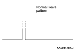
Wave pattern characteristics
Cause of problem
Open-circuit in the ignition primary circuit.
|