|
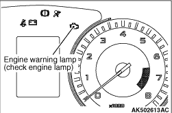
When the abnormal condition occurs with respect to the items of Multipoint Fuel Injection
(MPI) system shown in the table, the engine warning lamp is illuminated. When the lamp remains illuminated
after the engine start, or when the lamp is illuminated while the engine is running, check the
diagnosis code output. There are two methods for checking the indicator lamp burn out: When
the ignition switch is in ON position, the indicator lamp is illuminated, and then extinguished
few seconds later. When the ignition switch is in ON position and the engine starts, the indicator
lamp is extinguished.
|
Code No.
|
Diagnosis item
|
P0105
|
Manifold absolute pressure sensor system
|
P0110
|
Intake air temperature sensor system
|
P0115
|
Engine coolant temperature sensor system
|
P0122*1
|
Throttle position sensor (main) circuit low input
|
P0123*1
|
Throttle position sensor (main) circuit high input
|
P0125*1
|
Insufficient coolant temperature for closed loop fuel control
|
P0130
|
Oxygen sensor (front) system
|
P0133
|
Oxygen sensor (front) circuit slow response
|
P0134*1
|
Oxygen sensor (front) circuit no activity detected
|
P0135
|
Oxygen sensor (front) heater system
|
P0136
|
Oxygen sensor (rear) system
|
P0141
|
Oxygen sensor (rear) heater system
|
P0170
|
Abnormal fuel system
|
P0201
|
No. 1 injector system
|
P0202
|
No. 2 injector system
|
P0203
|
No. 3 injector system
|
P0204
|
No. 4 injector system
|
P0222*1
|
Throttle position sensor (sub) circuit low input
|
P0223*1
|
Throttle position sensor (sub) circuit high input
|
P0300*2
|
Random/multiple cylinder misfire detected
|
P0301*2
|
No. 1 cylinder misfire detected
|
P0302*2
|
No. 2 cylinder misfire detected
|
P0303*2
|
No. 3 cylinder misfire detected
|
P0304*2
|
No. 4 cylinder misfire detected
|
P0335*1
|
Crank angle sensor system
|
P0340*1
|
Camshaft position sensor system
|
P0420
|
Catalyst malfunction <M/T>
|
P0421
|
Catalyst malfunction <A/T>
|
P0443
|
Purge control solenoid valve system
|
P0500*1
|
Vehicle speed sensor system <M/T>
|
P0603*1
|
EEPROM malfunction
|
P0606*1
|
Engine-ECU main processor malfunction
|
P0630*1
|
Chassis number not programmed
|
P0638*1
|
Throttle valve control servo circuit range/performance problem
|
P0642*1
|
Throttle position sensor power supply
|
P0657*1
|
Throttle valve control servo relay circuit malfunction
|
P1021
|
Oil feeder control valve system
|
P1233*1
|
Trustful check throttle position sensor (main)
|
P1234*1
|
Trustful check throttle position sensor (sub)
|
P1235*1
|
Trustful check manifold absolute pressure sensor
|
P1236*1
|
A/D converter
|
P1237*1
|
Trustful check accelerator pedal position sensor
|
P1238*1
|
Manifold absolute pressure sensor trustful for torque monitoring
|
P1239*1
|
Trustful check engine speed
|
P1241*1
|
Torque monitoring
|
P1603*1
|
Battery backup circuit malfunction
|
P1676*1
|
Variant coding system
|
P2100*1
|
Throttle valve control servo circuit (open)
|
P2101*1
|
Throttle valve control servo magneto malfunction
|
P2122*1
|
Accelerator pedal position sensor (main) circuit low input
|
P2123*1
|
Accelerator pedal position sensor (main) circuit high input
|
P2127*1
|
Accelerator pedal position sensor (sub) circuit low input
|
P2128*1
|
Accelerator pedal position sensor (sub) circuit high input
|
P2135*1
|
Throttle position sensor (main and sub) range/performance problem
|
P2138*1
|
Accelerator pedal position sensor (main and sub) range/performance
problem
|
U0101*1
|
A/T-ECU time-out <A/T>
|
U0141*1
|
ETACS-ECU time-out
|
|
|
Refer to GROUP 00 - How to Use Troubleshooting/Inspection Service Points - Diagnosis
Function  . .
|
|
|
When the diagnosis sensitivity-up mode is selected in M.U.T.-III, the engine-ECU illuminates
the engine warning lamp and enters into the mode to store the corresponding diagnosis code upon
detecting a failure. Time for judgment from occurrence of a malfunction to storing of a diagnosis
code is shortened (from 4 seconds to 1 second). This function reduces work for checking a malfunction
phenomenon and repair completion after repair. To return to the sensitivity standard mode after selecting
the diagnosis sensitivity-up mode, it is necessary either to turn the ignition key to "LOCK"
(OFF) or to reselect the sensitivity standard mode on M.U.T.-III. The diagnosis codes and freeze
frame data stored in the sensitivity-up mode are automatically erased when the mode is returned
to the sensitivity standard mode. If they are needed, record them beforehand.
|
|
|
DIAGNOSIS PROCEDURE
- Connect M.U.T.-III and switch the diagnosis mode of the engine-ECU to the diagnosis
sensitivity-up mode to perform a test run.
- Read the diagnosis code and repair the malfunctioning part.
- Select the sensitivity standard mode on M.U.T.-III or turn the ignition switch to
the ON position again after turning it to "LOCK" (OFF) position once.
| note |
When the ignition switch is turned to the "LOCK" (OFF) position, the engine-ECU switches
the diagnosis mode from diagnosis sensitivity-up mode to diagnosis standard mode.
|
|
|
|
Reading service data or performing an actuator test using M.U.T.-III enables you to check
the vehicle body harnesses and components for abnormalities. Sensor input or output to the actuator
can be displayed in numerical values or graphs in the service data while in the actuator test
the actuator can be forced to drive (ON/OFF driving in the specified time).
|
|
|
DIAGNOSIS PROCEDURE
- Connect M.U.T.-III to perform inspection with the service data and actuator test
function.
- If any abnormality is found, inspect and repair vehicle body harnesses and components.
- After repair, check that input and output have returned to normal.
- If a failure code which is caused by inspection and repair work is generated, erase
the failure code.
- Disconnect M.U.T.-III and perform a test run to check that the malfunction phenomenon
is resolved.
|
Code No.
|
Diagnosis item
|
Control content during malfunction
|
P0115
|
Engine coolant temperature sensor system
|
Control as if the engine coolant temperature is 80°C.
|
P0122
|
Throttle position sensor (main) circuit low input
|
- Throttle opening degree is restricted.
- Throttle opening degree position is in default position if throttle position sensor
(sub) fails.
|
P0123
|
Throttle position sensor (main) circuit high input
|
- Throttle opening degree is restricted.
- Throttle opening degree position is in default position if throttle position sensor
(sub) fails.
|
P0125
|
Insufficient coolant temperature for closed loop fuel control
|
Control as if the engine coolant temperature is 80°C.
|
P0222
|
Throttle position sensor (sub) circuit low input
|
- Throttle opening degree is restricted.
- Throttle opening degree position is in default position if throttle position sensor
(main) fails.
|
P0223
|
Throttle position sensor (sub) circuit high input
|
- Throttle opening degree is restricted.
- Throttle opening degree position is in default position if throttle position sensor
(main) fails.
|
P0300
|
Random/multiple cylinder misfire detected
|
The supply of fuel to the misfiring cylinder can possibly be cut.
|
P0301
|
No. 1 cylinder misfire detected
|
The supply of fuel to the misfiring cylinder can possibly be cut.
|
P0302
|
No. 2 cylinder misfire detected
|
The supply of fuel to the misfiring cylinder can possibly be cut.
|
P0303
|
No. 3 cylinder misfire detected
|
The supply of fuel to the misfiring cylinder can possibly be cut.
|
P0304
|
No. 4 cylinder misfire detected
|
The supply of fuel to the misfiring cylinder can possibly be cut.
|
P0325
|
Detonation sensor system
|
Fix the ignition timing with an allowance against detonation.
|
P0340
|
Camshaft position sensor system
|
- Engine runs in learned pattern until
engine stops.
- Does not control variable valve timing (V.V.T.).
|
P0513
|
Immobilizer system
|
Engine start is prohibited.
|
P0606
|
Engine-ECU main processor malfunction
|
Throttle opening degree position is in default position.
|
P0622
|
Alternator FR terminal system
|
Prohibits alternator output suppression control against current consumers
(operates as a normal alternator).
|
P0638
|
Throttle valve control servo circuit range/performance problem
|
Throttle opening degree position is in default position.
|
P0642
|
Throttle position sensor power supply
|
Throttle opening degree position is in default position.
|
P0657
|
Throttle valve control servo relay circuit malfunction
|
Throttle opening degree position is in default position.
|
P1021
|
Oil feeder control valve system
|
V.V.T. phase angle becomes most retarded angle.
|
P1231
|
Trustful check active stability control (ASC) <Vehicles with
ASC>
|
Torque requested by active stability control (ASC) is ignored.
|
P1232
|
Fail-safe control system
|
Microcomputer is reset.
|
P1233
|
Trustful check throttle position sensor (main)
|
- Throttle opening degree is restricted.
- Throttle opening degree position is in default position if throttle position sensor
(sub) fails.
|
P1234
|
Trustful check throttle position sensor (sub)
|
- Throttle opening degree is restricted.
- Throttle opening degree position is in default position
if throttle position sensor (main) fails.
|
P1235
|
Trustful check manifold absolute pressure sensor
|
Fuel control is carried out using throttle opening degree and engine speed
in accordance with preset map.
|
P1236
|
A/D converter
|
Throttle opening degree position is in default position.
|
P1237
|
Trustful check accelerator pedal position sensor
|
Throttle opening degree position is in default position.
|
P1238
|
Manifold absolute pressure sensor trustful for torque monitoring
|
Throttle opening degree position is in default position.
|
P1239
|
Trustful check engine speed
|
Throttle opening degree position is in default position.
|
P1240
|
Trustful check ignition angle <Vehicles with ASC>
|
Ignition retard is not carried out
|
P1241
|
Torque monitoring
|
Throttle opening degree position is in default position.
|
P1242
|
Fail safe control monitoring
|
Throttle opening degree position is in default position.
|
P1243
|
Inquiry/response error
|
Microcomputer is reset.
|
P1244
|
RAM test for all area
|
Microcomputer is reset.
|
P1245
|
Cyclic RAM test (engine)
|
Microcomputer is reset.
|
P1247
|
Trustful check A/T <A/T>
|
Torque requested by A/T-ECU is ignored.
|
P1603
|
Battery backup circuit malfunction
|
All diagnosis codes are stored once failure judgment is completed.
|
P2100
|
Throttle valve control servo circuit (open)
|
Throttle opening degree position is in default position.
|
P2101
|
Throttle valve control servo magneto malfunction
|
Throttle opening degree position is in default position.
|
P2122
|
Accelerator pedal position sensor (main) circuit low input
|
- Throttle opening degree is restricted.
- Throttle opening degree position is in default position if accelerator pedal position
sensor (sub) fails.
|
P2123
|
Accelerator pedal position sensor (main) circuit high input
|
- Throttle opening degree is restricted.
- Throttle opening degree position is in default position if accelerator pedal position
sensor (sub) fails.
|
P2127
|
Accelerator pedal position sensor (sub) circuit low input
|
- Throttle opening degree is restricted.
- Throttle opening degree position is in default position
if accelerator pedal position sensor (main) fails.
|
P2128
|
Accelerator pedal position sensor (sub) circuit high input
|
- Throttle opening degree is restricted.
- Throttle opening degree position is in default position
if accelerator pedal position sensor (main) fails.
|
P2135
|
Throttle position sensor (main and sub) range/performance
problem
|
Throttle opening degree position is in default position.
|
P2138
|
Accelerator pedal position sensor (main and sub) range/performance problem
|
- Throttle opening degree is restricted.
- Throttle opening degree position is in default position if accelerator pedal position
sensor (sub) fails.
|
U0167
|
KOS-ECU <Vehicles with KOS> or WCM <Vehicles
with WCM> communication error
|
Engine start is prohibited.
|