|
|
- Check battery (Refer to GROUP 54A - Battery - On-vehicle
Service - Battery Test
 ). ).
|
|
|
Q.
Is the check result normal?
|
|
|
Q.
Is the diagnosis code set?
|
|
|
 Inspection chart for diagnosis codes (Refer to ) Inspection chart for diagnosis codes (Refer to )
|
|
|
|
|
|
OK: Operating sound of fuel pump can be heard.
|
|
|
Q.
Is the check result normal?
|
|
|
 Check fuel pump system (Refer to Inspection Procedure 21 ) Check fuel pump system (Refer to Inspection Procedure 21 )
|
|
|
|
|
|
Q.
Is the check result normal?
|
|
|
Replace the timing chain.
|
|
|
|
|
|
Q.
Is the check result normal?
|
|
|
Clean throttle body (throttle valve portion) (Refer to ).
|
|
|
|
|
|
- Refer to Data List Reference Table .
- Item 2: Crank angle sensor
|
|
|
Q.
Is the check result normal?
|
|
|
Check crank angle sensor system (Refer to Code No. P0335 ).
|
|
|
|
|
|
- Remove the spark plug and install it to the ignition coil.
- Connect the ignition coil connector.
- Disconnect all injector connectors.
- At the engine start, check each spark plug produces a spark.
|
|
|
Q.
Is the check result normal?
|
|
|
Check ignition circuit system (Refer to Inspection Procedure 23 )
|
|
|
|
|
|
Q.
Is the check result normal?
|
|
|
Repair or replace the connector.
|
|
|
|
|
|
- Check injector relay itself (Refer to ).
|
|
|
Q.
Is the check result normal?
|
|
|
Replace the injector relay.
|
|
|
|
|
|
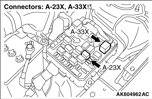
- Remove relay, and measure at relay box side.
- Resistance between terminal No. 2 and earth.
|
|
|
OK: Continuity (2 Ω or less)
|
|
|
Q.
Is the check result normal?
|
|
|
Check and repair harness between A-23X (terminal
No. 2) injector relay connector and body earth.
- Check earthing line for open circuit and damage.
|
|
|
|
|
|
- Remove relay, and measure at relay box side.
- Ignition switch: ON
- Voltage between terminal No. 1 and earth.
|
|
|
Q.
Is the check result normal?
|
|
|
Q.
Is the check result normal?
|
|
|
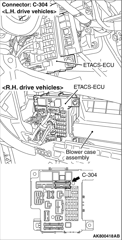
Check and repair harness between C-304 (terminal
No. 10) ETACS-ECU connector and A-23X (terminal No. 1) injector relay connector.
- Check power supply line for open/short circuit.
|
|
|
|
|
|
Repair or replace the connector.
|
|
|
|
|
|
- Remove relay, and measure at relay box side.
- Ignition switch: ON
- Voltage between terminal No. 4 and earth.
|
|
|
Q.
Is the check result normal?
|
|
|
Q.
Is the check result normal?
|
|
|
Check and repair harness between A-33X (terminal
No. 2) engine control relay connector and A-23X (terminal No. 4) injector relay connector.
- Check power supply line for open/short circuit.
|
|
|
|
|
|
Repair or replace the connector.
|
|
|
|
|
|
- Disconnect connector, and measure at harness side.
- Ignition switch: ON
- Voltage between terminal No. 1 and earth.
|
|
|
Q.
Are the check results normal?
|
|
|
- Check power supply line for open/short circuit.
|
|
|
Q.
Is the check result normal?
|
|
|
Repair the damaged harness wire.
|
|
|
|
|
|
Q.
Is the check result normal?
|
|
|
Check and repair harness between C-304 (terminal
No. 10) ETACS-ECU connector and A-23X (terminal No. 1) injector relay connector.
- Check power supply line for damage.
|
|
|
|
|
|
Repair or replace the connector.
|
|
|
|
|
|
Q.
Is the check result normal?
|
|
|
Repair or replace the connector.
|
|
|
|
|
|
- Check power supply line for damage.
|
|
|
Q.
Is the check result normal?
|
|
|
Repair the damaged harness wire.
|
|
|
|
|
|
- Check power supply line for damage.
|
|
|
Q.
Is the check result normal?
|
|
|
Repair the damaged harness wire.
|
|
|
|
|
|
- Check injector for operating sound at engine cranking (Refer to ).
|
|
|
Q.
Can operating sound be heard?
|
|
|
Check the injector system of the defective
cylinder.
(Refer to Code No. P0201: No. 1 injector system ).
(Refer to Code No. P0202: No. 2 injector system ).
(Refer to Code No. P0203: No. 3 injector system ).
(Refer to Code No. P0204: No. 4 injector system ).
|
|
|
|
|
|
- Fuel pressure measurement (Refer to ).
|
|
|
Q.
Is the check result normal?
|
|
|
- After replacing the engine-ECU, re-check the trouble symptoms.
|
|
|
Q.
Does trouble symptom persist?
|
|
|
Check for foreign matters (water, diesel fuel, etc.) in fuel and replace if necessary.
|
|
|
|