|
|
- Check battery (Refer to GROUP 54A - Battery - On-vehicle
Service - Battery Test
 ). ).
|
|
|
Q.
Is the check result normal?
|
|
|
Q.
Is the check result normal?
|
|
|
 Repair or replace the connector. Repair or replace the connector.
|
|
|
|
|
|
- Disconnect connector, and measure at harness side.
- Ignition switch: ON
- Voltage between terminal No. 3 and earth.
|
|
|
Q.
Is the check result normal?
|
|
|
Q.
Is the check result normal?
|
|
|

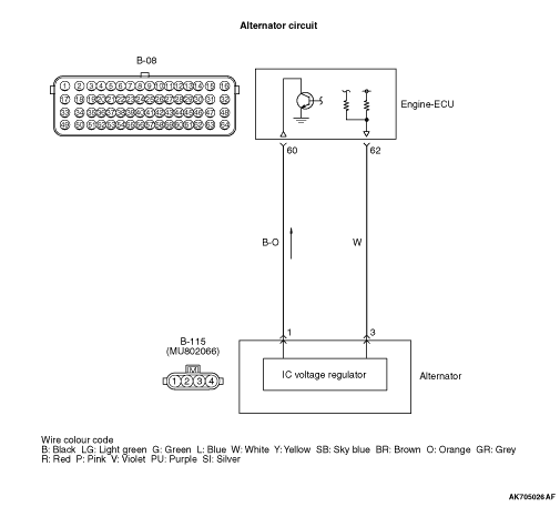
Check and repair harness between B-115 (terminal
No. 3) alternator connector and B-08 (terminal No. 62) engine-ECU connector.
- Check power supply line for open/short circuit.
|
|
|
|
|
|
Repair or replace the connector.
|
|
|
|
|
|
- Disconnect connector, and measure at harness side.
- Connect special tool test harness (MB991658) to all terminals except the terminal No.1.
- Ignition switch: ON
- Voltage between terminal No. 1 and earth.
|
|
|
Q.
Is the check result normal?
|
|
|
Q.
Is the check result normal?
|
|
|
Repair or replace the connector.
|
|
|
|
|
|
- Check output line for short circuit.
|
|
|
Q.
Is the check result normal?
|
|
|
Repair the damaged harness wire.
|
|
|
|
|
|
- Disconnect engine-ECU connector, and connect special tool power plant ECU
check harness (MB992110) to measure at connector for inspection.
- Engine: Idle operation after warm-up
- Transmission: Neutral <M/T> or P range <A/T>
- Cooling fan: Not operated
- Voltage between terminal No. 60 and earth.
|
|
|
OK: Voltage increases when the headlamps are extinguished→illuminated.
|
|
|
Q.
Is the check result normal?
|
|
|
Q.
Does the trouble symptom persist?
|
|
|
Intermittent malfunction (Refer to GROUP 00 - How to Use Troubleshooting/Inspection
Service Points - How to Cope with Intermittent Malfunctions ).
|
|
|
|