Inspection Procedure 20: Fuel Pump System


OPERATION


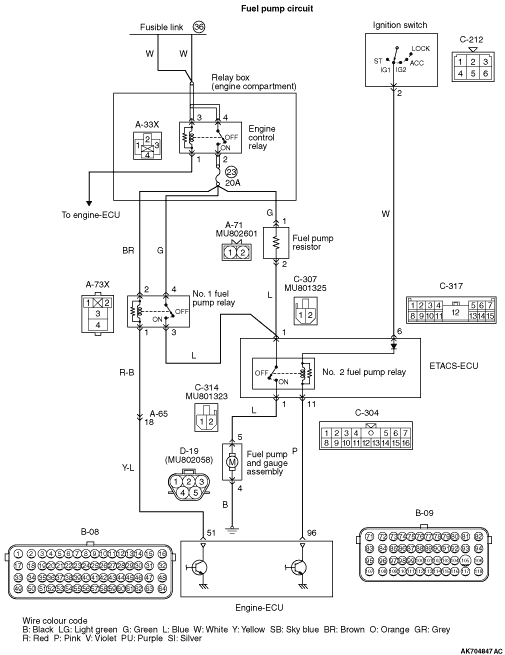
  • The power source is supplied from engine control relay (terminal No. 2) to No. 1 fuel pump relay (terminal No. 4) and fuel pump register (terminal No. 1).
  • The battery voltage is applied to No. 1 fuel pump relay (terminal No. 2) from engine control relay (terminal No. 2).
  • The battery voltage is applied to No. 2 fuel pump relay (C-317 ETACS-ECU connector terminal No. 6) inside ETACS-ECU from the ignition switch (terminal No. 2).
  • During cranking or when the engine is running, the engine-ECU (terminal No. 96) turns ON the power transistor inside the unit, and then makes the current flow into No. 2 fuel pump relay (C-304 ETACS-ECU connector terminal No. 11) inside ETACS-ECU to turn ON the relay. When No. 2 fuel pump relay is turned ON, the power source for driving the fuel pump is supplied to the fuel pump (terminal No. 5) from No. 2 fuel pump relay (C-314 ETACS-ECU connector terminal No. 1).
  • When the engine is running with low load, the engine-ECU (terminal No. 51) turns OFF the power transistor inside the unit not to make the current flow into No. 1 fuel pump relay (terminal No. 1), and then turns OFF the relay.
  • When the engine is running with high load, the engine-ECU (terminal No. 51) turns ON the power transistor inside the unit to make the current flow into No. 1 fuel pump relay (terminal No. 1), and then turns ON the relay. This supplies the power source for driving the fuel pump to No. 2 fuel pump relay (C-307 ETACS-ECU connector terminal No. 1) inside ETACS-ECU from No. 1 fuel pump relay (terminal No. 3).

FUNCTION


  • During cranking or when the engine is running, the engine-ECU turns on the fuel pump relay, and supplies the power source to the fuel pump for driving.
  • The engine-ECU, when the engine is running with low load, supplies the power source to the fuel pump via the resistor. Also the engine ECU, when the engine is running with high load, supplies the power source directly to increase the discharging amount of the fuel pump.

PROBABLE CAUSES


  • Failed No. 1 fuel pump relay
  • Failed No. 2 fuel pump relay in the ETACS-ECU
  • Failed fuel pump
  • Failed fuel pump resistor
  • Open/short circuit or harness damage in fuel pump drive circuit, or loose connector contact.
  • Failed engine-ECU

DIAGNOSIS PROCEDURE


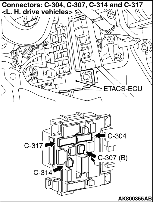
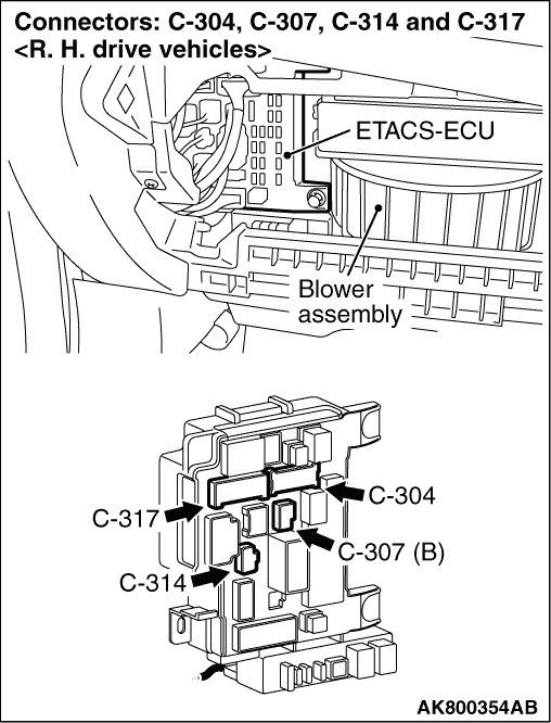
STEP 1. Connector check: C-304, C-307, C-314 and C-317 ETACS-ECU connectors


Q. Are the check results normal?

Go to Step 2.
Repair or replace the connector.

STEP 2. Check No. 2 fuel pump relay itself.


  • Check No. 2 fuel pump relay itself. (Refer to ).

Q. Is the check result normal?

Go to Step 3.
Replace the ETACS-ECU.

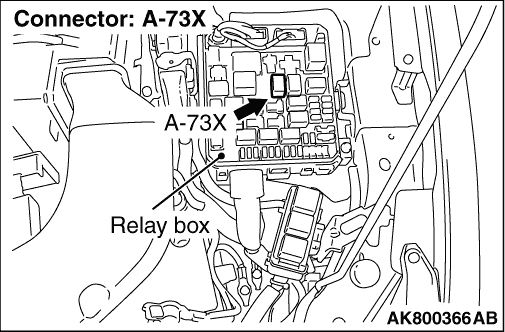
STEP 3. Connector check: A-73X No. 1 fuel pump relay connector


Q. Is the check result normal?

Go to Step 4.
Repair or replace the connector.

STEP 4. Check No. 1 fuel pump relay itself.


  • Check No. 1 fuel pump relay itself. (Refer to ).

Q. Is the check result normal?

Go to Step 5.
Replace the No. 1 fuel pump relay.

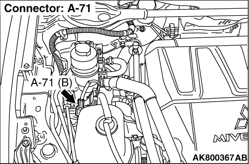
STEP 5. Connector check: A-71 fuel pump resistor connector


Q. Is the check result normal?

Go to Step 6.
Repair or replace the connector.

STEP 6. Check fuel pump resistor itself.


  • Check fuel pump resistor itself (Refer to ).

Q. Is the check result normal?

Go to Step 7.
Replace the fuel pump resistor.

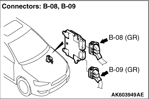
STEP 7. Connector check: B-09 engine-ECU connector


Q. Is the check result normal?

Go to Step 8.
Repair or replace the connector.

STEP 8. Perform voltage measurement at B-09 engine-ECU connector.


  • Disconnect connector, and measure at harness side.
  • Ignition switch: ON
  • Voltage between terminal No. 96 and earth.
OK: System voltage

Q. Is the check result normal?

Go to Step 9.

    Check and repair harness between B-09 (terminal No. 96) engine-ECU connector and C-304 (terminal No. 11) ETACS-ECU connector.

    • Check output line for open/short circuit.

STEP 9. Connector check: B-08 engine-ECU connector


Q. Is the check result normal?

Go to Step 10.
Repair or replace the connector.

STEP 10. Perform voltage measurement at B-08 engine-ECU connector.


  • Disconnect connector, and measure at harness side.
  • Ignition switch: ON
  • Voltage between terminal No. 51 and earth.
OK: System voltage

Q. Is the check result normal?

Go to Step 13.
Go to Step 11.

STEP 11. Check harness between A-73X (terminal No. 1) No. 1 fuel pump relay connector and B-08 (terminal No. 51) engine-ECU connector.


note Before checking harness, check intermediate connector A-65, and repair if necessary.

  • Check output line for open/short circuit.

Q. Is the check result normal?

Go to Step 12.
Repair the damaged harness wire.

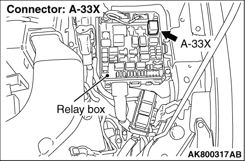
STEP 12. Connector check: A-33X engine control relay connector


Q. Is the check result normal?


    Check and repair harness between A-73X (terminal No. 2) No. 1 fuel pump relay connector and A-33X (terminal No. 2) engine control relay connector.

    • Check power supply line for open/short circuit.
Repair or replace the connector.

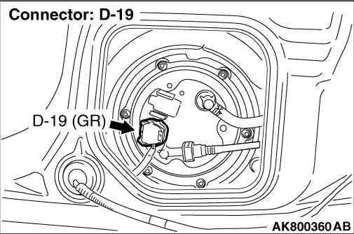
STEP 13. Connector check: D-19 fuel pump connector


Q. Is the check result normal?

Go to Step 14.
Repair or replace the connector.

STEP 14. Check fuel pump operations.


  • Check fuel pump operations (Refer to ).

Q. Is the check result normal?

Go to Step 15.
Replace the fuel pump and gage assembly.

STEP 15. Perform resistance measurement at D-19 fuel pump connector.


  • Disconnect connector, and measure at harness side.
  • Resistance between terminal No. 4 and earth.
OK: Continuity (2 Ω or less)

Q. Is the check result normal?

Go to Step 16.

    Check and repair harness between D-19 (terminal No. 4) fuel pump connector and body earth.

    • Check earthing line for open circuit and damage.

STEP 16. Perform voltage measurement at D-19 fuel pump connector.


  • Disconnect connector, and measure at harness side.
  • Disconnect B-09 engine-ECU connector, and short-circuit terminal No. 73 and No. 96 to the earth.
  • Ignition switch: ON
  • Voltage between terminal No. 5 and earth.
OK: System voltage

Q. Is the check result normal?

Go to Step 22.
Go to Step 17.

STEP 17. Check harness between D-19 (terminal No. 5) fuel pump connector and C-314 (terminal No. 1) ETACS-ECU connector.


  • Check power supply line for open/short circuit.

Q. Is the check result normal?

Go to Step 18.
Repair the damaged harness wire.

STEP 18. Check harness between A-71 (terminal No. 2) fuel pump resistor connector and C-307 (terminal No. 1) ETACS-ECU connector.


  • Check power supply line for open/short circuit.

Q. Is the check result normal?

Go to Step 19.
Repair the damaged harness wire.

STEP 19. Connector check: A-33X engine control relay connector


Q. Is the check result normal?

Go to Step 20.
Repair or replace the connector.

STEP 20. Check harness between A-33X (terminal No. 2) engine control relay connector and A-71 (terminal No. 1) fuel pump resistor connector.


  • Check power supply line for open/short circuit.

Q. Is the check result normal?

Go to Step 21.
Repair the damaged harness wire.

STEP 21. Check harness between A-73X (terminal No. 3) No. 1 fuel pump relay connector and C-307 (terminal No. 1) ETACS-ECU connector.


  • Check power supply line for short circuit.

Q. Is the check result normal?


    Check and repair harness between B-09 (terminal No. 96) engine-ECU connector and C-304 (terminal No. 11) ETACS-ECU connector.

    • Check output line for damage.
Repair the damaged harness wire.

STEP 22. Perform voltage measurement at C-307 ETACS-ECU connector.


  • Disconnect connector, and measure at harness side.
  • Disconnect A-71 fuel pump resistor connector.
  • Disconnect B-08 engine-ECU connector, and short-circuit terminal No. 51 to the earth.
  • Ignition switch: ON
  • Voltage between terminal No. 1 and earth.
OK: System voltage

Q. Is the check result normal?

Go to Step 27.
Go to Step 23

STEP 23. Check harness between A-73X (terminal No. 3) No. 1 fuel pump relay connector and C-307 (terminal No. 1) ETACS-ECU connector.


  • Check power supply line for open circuit.

Q. Is the check result normal?

Go to Step 24.
Repair the damaged harness wire.

STEP 24. Connector check: A-33X engine control relay connector


Q. Is the check result normal?

Go to Step 25.
Repair or replace the connector.

STEP 25. Check harness between A-73X (terminal No. 4) No. 1 fuel pump relay connector and A-33X (terminal No. 2) engine control relay connector.


  • Check power supply line for open/short circuit.

Q. Is the check result normal?

Go to Step 26.
Repair the damaged harness wire.

STEP 26. Check harness between A-73X (terminal No. 1) No. 1 fuel pump relay connector and B-08 (terminal No. 51) engine-ECU connector.


note Before checking harness, check intermediate connector A-65, and repair if necessary.

  • Check output line for damage.

Q. Is the check result normal?


    Check and repair harness between A-73X (terminal No. 2) No. 1 fuel pump relay connector and A-33X (terminal No. 2) engine control relay connector.

    • Check power supply line for damage.
Repair the damaged harness wire.

STEP 27. Check harness between D-19 (terminal No. 5) fuel pump connector and C-314 (terminal No. 1) ETACS-ECU connector.


  • Check power supply line for damage.

Q. Is the check result normal?

Go to Step 28.
Repair the damaged harness wire.

STEP 28. Check harness between A-71 (terminal No. 2) fuel pump resistor connector and C-307 (terminal No. 1) ETACS-ECU connector.


  • Check power supply line for damage.

Q. Is the check result normal?

Go to Step 29.
Repair the damaged harness wire.

STEP 29. Connector check: A-33X engine control relay connector


Q. Is the check result normal?

Go to Step 30.
Repair or replace the connector.

STEP 30. Check harness between A-33X (terminal No. 2) engine control relay connector and A-71 (terminal No. 1) fuel pump resistor connector.


  • Check power supply line for damage.

Q. Is the check result normal?

Go to Step 31.
Repair the damaged harness wire.

STEP 31. Check harness between A-73X (terminal No. 3) No. 1 fuel pump relay connector and C-307 (terminal No. 1) ETACS-ECU connector.


  • Check power supply line for damage.

Q. Is the check result normal?

Go to Step 32.
Repair the damaged harness wire.

STEP 32. Check harness between A-73X (terminal No. 4) No. 1 fuel pump relay connector and A-33X (terminal No. 2) engine control relay connector.


  • Check power supply line for damage.

Q. Is the check result normal?

Go to Step 33.
Repair the damaged harness wire.

STEP 33. M.U.T.-III actuator test


  • Refer to Actuator Test Reference Table .

  1. Item 9: Fuel pump

Q. Is the check result normal?

Intermittent malfunction (Refer to GROUP 00 - How to Use Troubleshooting/Inspection Service Points - How to Cope with Intermittent Malfunctions ).
Replace the engine-ECU.