|
|
- Check battery (Refer to GROUP 54A - Battery - On-vehicle
Service - Battery Test
 ). ).
|
|
|
Q.
Is the check result normal?
|
|
|
OK:
ON (ignition switch: ST)
OFF (ignition switch: ON)
|
|
|
Q.
Is the check result normal?
|
|
|
Q.
Is the check result normal?
|
|
|
 Repair or replace the connector. Repair or replace the connector.
|
|
|
|
|
|
- Disconnect connector, and measure at harness side.
- Ignition switch: ST
- Voltage between terminal No. 105 and earth.
|
|
|
Q.
Is the check result normal?
|
|
|
Q.
Are the check results normal?
|
|
|
Repair or replace the connector.
|
|
|
|
|
|
- Disconnect connector, and measure at harness side.
- Ignition switch: ST
- Voltage between terminal No. 7 and earth.
|
|
|
Q.
Is the check result normal?
|
|
|
Q.
Is the check result normal?
|
|
|
Repair or replace the connector.
|
|
|
|
|
|
- Check ignition switch itself (Refer to GROUP 54A - Ignition Switch - Inspection - Ignition
Switch Continuity Check ).
|
|
|
Q.
Is the check result normal?
|
|
|

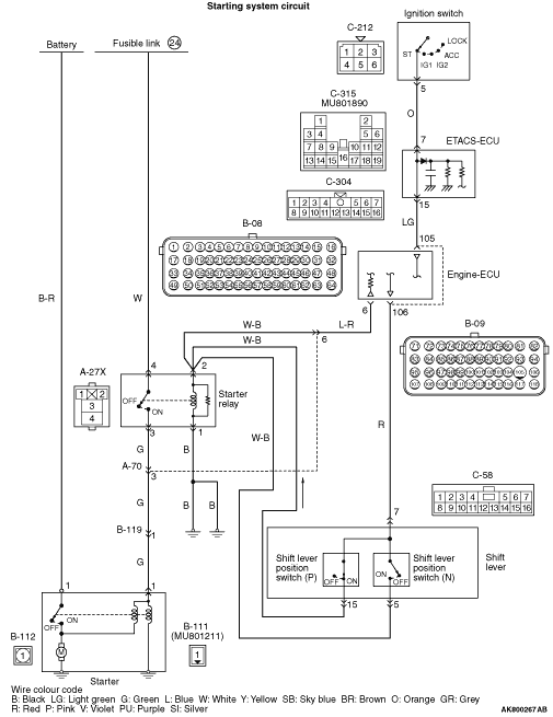
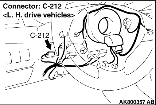
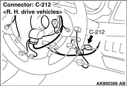
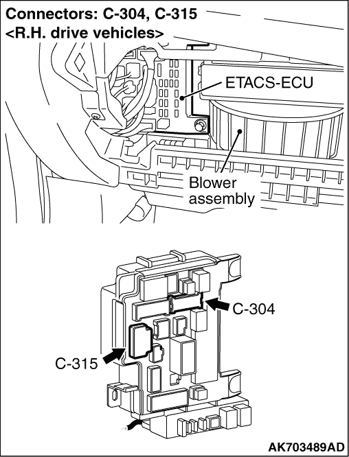
Check and repair harness between C-212 (terminal
No. 5) ignition switch connector and C-315 (terminal No. 7) ETACS-ECU connector.
- Check power supply line for open/short circuit.
|
|
|
|
|
|
Replace the ignition switch.
|
|
|
|
|
|
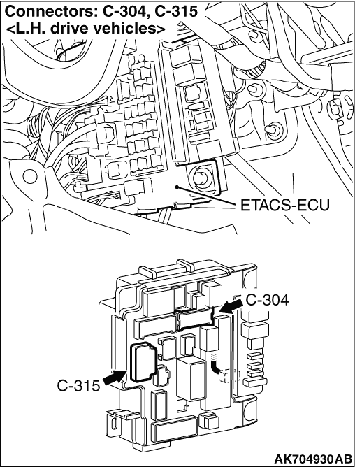
- Disconnect connectors, and measure at ETACS-ECU side.
- Continuity check between terminal No. 7 (C-315) and No. 15 (C-304)
|
|
|
Q.
Is the check result normal?
|
|
|
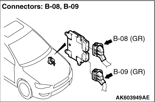
Check and repair harness between C-304 (terminal
No. 15) ETACS-ECU connector and B-09 (terminal No. 105) engine-ECU connector.
- Check power supply line for open/short circuit.
|
|
|
|
|
|
Q.
Are the check results normal?
|
|
|
Repair or replace the connector.
|
|
|
|
|
|
- Disconnect connectors, and measure at ETACS-ECU side.
- Continuity check between terminal No. 7 (C-315) and No. 15 (C-304)
|
|
|
Q.
Is the check result normal?
|
|
|
- Check power supply line for damage.
|
|
|
Q.
Is the check result normal?
|
|
|
Repair the damaged harness wire.
|
|
|
|
|
|
- Check power supply line for damage.
|
|
|
Q.
Is the check result normal?
|
|
|
Repair the damaged harness wire.
|
|
|
|
|
|
OK:
ON (ignition switch: ST)
OFF (ignition switch: ON)
|
|
|
Q.
Is the check result normal?
|
|
|
Intermittent malfunction (Refer to GROUP 00 - How to Use Troubleshooting/Inspection
Service Points - How to Cope with Intermittent Malfunctions ).
|
|
|
|
|
|
Q.
Is the check result normal?
|
|
|
Repair or replace the connector.
|
|
|
|
|
|
- Check starter relay itself (Refer to GROUP 16 - Starting
System - On-vehicle Service - Starter Relay Continuity Check ).
|
|
|
Q.
Is the check result normal?
|
|
|
Replace the starter relay.
|
|
|
|
|
|
- Remove relay, and measure at relay box side.
- Resistance between terminal No. 1 and earth.
|
|
|
OK: Continuity (2 Ω or less)
|
|
|
Q.
Is the check result normal?
|
|
|
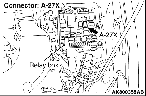
Check and repair harness between A-27X (terminal
No. 1) starter relay connector and body earth.
- Check earthing line for open circuit and damage.
|
|
|
|
|
|
- Remove relay, and measure at relay box side.
- Transmission: P or N range
- Ignition switch: ST
- Voltage between terminal No. 2 and earth.
|
|
|
Q.
Is the check result normal?
|
|
|
Q.
Is the check result normal?
|
|
|
Repair or replace the connector.
|
|
|
|
|
|
- Check power supply line for open/short circuit.
|
|
|
Q.
Is the check result normal?
|
|
|
Repair the damaged harness wire.
|
|
|
|
|
|
Q.
Is the check result normal?
|
|
|
Repair or replace the connector.
|
|
|
|
|
|
- Check power supply line for open/short circuit.
|
|
|
Q.
Is the check result normal?
|
|
|
Repair the damaged harness wire.
|
|
|
|
|
|
Q.
Is the check result normal?
|
|
|
Repair or replace the connector.
|
|
|
|
|
|
- Check output line for short circuit.
|
|
|
Q.
Is the check result normal?
|
|
|
Repair the damaged harness wire.
|
|
|
|
|
|
- After replacing the shift lever, re-check the trouble symptoms.
|
|
|
Q.
Does the trouble symptom persist?
|
|
|
- Remove relay, and measure at relay box side.
- Voltage between terminal No. 4 and earth.
|
|
|
Q.
Is the check result normal?
|
|
|
Check and repair harness between battery and
A-27X (terminal No. 4) starter relay connector.
- Check power supply line for open/short circuit.
|
|
|
|
|
|
Q.
Is the check result normal?
|
|
|
Repair or replace the connector.
|
|
|
|
|
|
- Disconnect connector, and measure at harness side.
- Transmission: P or N range
- Ignition switch: ST
- Voltage between terminal No. 1 and earth.
|
|
|
Q.
Is the check result normal?
|
|
|
- Check output line for open/short circuit.
|
|
|
Q.
Is the check result normal?
|
|
|
Repair the damaged harness wire.
|
|
|
|
|
|
Q.
Is the check result normal?
|
|
|
Repair or replace the connector.
|
|
|
|
|
|
- Check power supply line for damage.
|
|
|
Q.
Is the check result normal?
|
|
|
Repair the damaged harness wire.
|
|
|
|
|
|
Q.
Is the check result normal?
|
|
|
Repair or replace the connector.
|
|
|
|
|
|
- Check power supply line for damage.
|
|
|
Q.
Is the check result normal?
|
|
|
Repair the damaged harness wire.
|
|
|
|
|
|
- Check power supply line for damage.
|
|
|
Q.
Is the check result normal?
|
|
|
Repair the damaged harness wire.
|
|
|
|
|
|
- Check output line for damage.
|
|
|
Q.
Is the check result normal?
|
|
|
Repair the damaged harness wire.
|
|
|
|
|
|
Q.
Is the check result normal?
|
|
|
Repair or replace the connector.
|
|
|
|
|
|
- Disconnect connector, and measure at harness side.
- Voltage between terminal No. 1 and earth.
|
|
|
Q.
Is the check result normal?
|
|
|
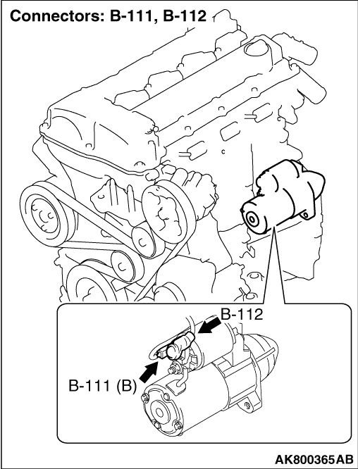
Check and repair harness between battery and
B-112 (terminal No. 1) starter connector.
- Check power supply line for open/short circuit.
|
|
|
|
|
|
- Check power supply line for damage.
|
|
|
Q.
Is the check result normal?
|
|
|
Repair the damaged harness wire.
|
|
|
|