|
|
- Refer to Data List Reference Table
 . .
- Item AD: Oxygen sensor (rear)
|
|
|
Q.
Is the check result normal?
|
|
|
 Intermittent malfunction (Refer to GROUP 00 - How to Use Troubleshooting/Inspection
Service Points - How to Cope with Intermittent Malfunctions ). Intermittent malfunction (Refer to GROUP 00 - How to Use Troubleshooting/Inspection
Service Points - How to Cope with Intermittent Malfunctions ).
|
|
|
|
|
|
Q.
Is the check result normal?
|
|
|
 Repair or replace the connector. Repair or replace the connector.
|
|
|
|
|
|
- Disconnect connector, and measure at harness side.
- Resistance between terminal No. 4 and earth.
|
|
|
OK: Continuity (2 Ω or less)
|
|
|
Q.
Is the check result normal?
|
|
|
Q.
Is the check result normal?
|
|
|
Repair or replace the connector.
|
|
|
|
|
|
- Check earthing line for open circuit and damage.
|
|
|
Q.
Is the check result normal?
|
|
|
Repair the damaged harness wire.
|
|
|
|
|
|
- Refer to Data List Reference Table .
- Item AD: Oxygen sensor (rear)
|
|
|
Q.
Is the check result normal?
|
|
|
Intermittent malfunction (Refer to GROUP 00 - How to Use Troubleshooting/Inspection
Service Points - How to Cope with Intermittent Malfunctions ).
|
|
|
|
|
|
- Use special tool test harness (MB991658) to connect connector, and measure
at pick-up harness.
- Accelerate the engine at full throttle in the 2nd gear to keep the engine speed
at 3,500 r/min or more.
- Voltage between terminal No. 3 and earth.
|
|
|
Q.
Is the check result normal?
|
|
|
- Check oxygen sensor (rear) (Refer to ).
|
|
|
Q.
Is the check result normal?
|
|
|
Replace the oxygen sensor (rear).
|
|
|
|
|
|
Q.
Is the check result normal?
|
|
|
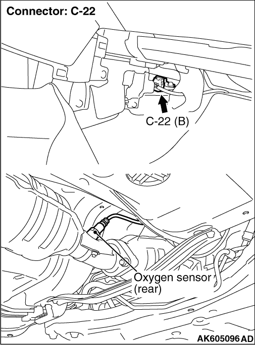
Check intermediate connector A-11, and repair
if necessary.If intermediate connector is normal, check and repair harness between C-22 (terminal No.
3) oxygen sensor (rear) connector and B-08 (terminal No. 40) engine-ECU connector.
- Check output line for short circuit.
|
|
|
|
|
|
Repair or replace the connector.
|
|
|
|
|
|
Q.
Is the check result normal?
|
|
|
Repair or replace the connector.
|
|
|
|
|
|
- Disconnect engine-ECU harness, and connect special tool power plant ECU check
harness (MB992110) to measure at connector for inspection.
- Accelerate the engine at full throttle in the 2nd gear to keep the engine speed
at 3,500 r/min or more.
- Voltage between terminal No. 40 and earth.
|
|
|
Q.
Is the check result normal?
|
|
|
Q.
Is the check result normal?
|
|
|
Check intermediate connector A-11, and repair
if necessary.If intermediate connector is normal, check and repair harness between C-22 (terminal No.
3) oxygen sensor (rear) connector and B-08 (terminal No. 40) engine-ECU connector.
- Check output line for open circuit and damage.
|
|
|
|
|
|
Repair or replace the connector.
|
|
|
|