Code No. P0365: Exhaust Camshaft Position Sensor System

OPERATION
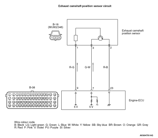
- Power is supplied to the exhaust camshaft position sensor
(terminal No. 1) from the engine-ECU (terminal No. 9) and is earthed to the engine-ECU (terminal
No. 23) from the exhaust camshaft position sensor (terminal No. 2).
- A power voltage of 5 V is applied to the exhaust camshaft position sensor output
terminal (terminal No. 3) from the engine-ECU (terminal No. 7).
FUNCTION
- The exhaust camshaft position sensor detects the top
dead centre on the compression stroke of the No. 1 cylinder and inputs a pulse signal to the engine-ECU.
TROUBLE JUDGMENT
Check Condition
- Engine is running.
- A pulse signal from the crank angle sensor continues 264 times and engine speed
is less than 440 r/min.
- An exhaust camshaft position sensor signal pattern is not normal
- Malfunction is detected twice or more since the ignition switch is turned ON.
- Engine is running.
- An exhaust camshaft position sensor signal pattern is not normal for 2 seconds and
engine speed is more than 440 r/min.
- Does not control variable valve timing (V.V.T.).
PROBABLE CAUSES
- Failed exhaust camshaft position sensor
- Open/short circuit or harness damage in exhaust camshaft position sensor circuit
or loose connector contact
- Failed engine-ECU
DIAGNOSIS PROCEDURE |
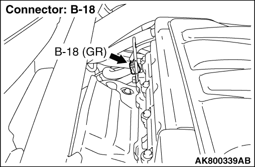
STEP 1. Connector check: B-18 exhaust camshaft position sensor connector |
Q.
Is the check result normal?
|
 Go to Step 2. Go to Step 2. |
|
 Repair or replace the connector. Repair or replace the connector. |
|
STEP 2. Perform voltage measurement at B-18 exhaust camshaft position sensor connector. |
|
| OK: 4.9 - 5.1 V |
Q.
Is the check result normal?
|
| Go to Step 6. |
|
| Go to Step 3. |
|
STEP 3. Connector check: B-08 engine-ECU connector |
Q.
Is the check result normal?
|
| Go to Step 4. |
|
| Repair or replace the connector. |
|
STEP 4. Check harness between B-18 (terminal No. 3) exhaust camshaft position sensor connector and B-08 (terminal No. 7) engine-ECU connector. |
|
Q.
Is the check result normal?
|
| Go to Step 5. |
|
| Repair the damaged harness wire. |
|
STEP 5. M.U.T.-III diagnosis code |
|
Q.
Is diagnosis code set?
|
| Replace the engine-ECU. |
|
Intermittent malfunction (Refer to GROUP 00 - How to Use Troubleshooting/Inspection
Service Points - How to Cope with Intermittent Malfunctions  ). ). |
|
STEP 6. Perform voltage measurement at B-18 exhaust camshaft position sensor connector. |
|
| OK: 4.9 - 5.1 V |
Q.
Is the check result normal?
|
| Go to Step 9. |
|
| Go to Step 7. |
|
STEP 7. Connector check: B-08 engine-ECU connector |
Q.
Is the check result normal?
|
| Go to Step 8. |
|
| Repair or replace the connector. |
|
STEP 8. Check harness between B-18 (terminal No. 1) exhaust camshaft position sensor connector and B-08 (terminal No. 9) engine-ECU connector. |
|
Q.
Is the check result normal?
|
| Go to Step 5. |
|
| Repair the damaged harness wire. |
|
STEP 9. Perform resistance measurement at B-18 exhaust camshaft position sensor connector. |
|
| OK: Continuity (2 Ω or less) |
Q.
Is the check result normal?
|
| Go to Step 12. |
|
| Go to Step 10. |
|
STEP 10. Connector check: B-08 engine-ECU connector |
Q.
Is the check result normal?
|
| Go to Step 11. |
|
| Repair or replace the connector. |
|
STEP 11. Check harness between B-18 (terminal No. 2) exhaust camshaft position sensor connector and B-08 (terminal No. 23) engine-ECU connector. |
|
Q.
Is the check result normal?
|
| Go to Step 5. |
|
| Repair the damaged harness wire. |
|
STEP 12. Perform output wave pattern measurement at B-18 exhaust camshaft position sensor connector (Using an oscilloscope). |
|
| OK: Waveforms should be displayed on inspection procedure using an oscilloscope
(Refer to ), its maximum value should be 4.8 V or more, and
its minimum value should be 0.6 V or less. There must be no noise in the output wave pattern. |
Q.
Is the check result normal?
|
| Go to Step 5. |
|
| Go to Step 13. |
|
STEP 13. Connector check: B-08 engine-ECU connector |
Q.
Is the check result normal?
|
| Go to Step 14. |
|
| Repair or replace the connector. |
|
STEP 14. Check harness between B-18 (terminal No. 1) exhaust camshaft position sensor connector and B-08 (terminal No. 9) engine-ECU connector. |
|
Q.
Is the check result normal?
|
| Go to Step 15. |
|
| Repair the damaged harness wire. |
|
STEP 15. Check harness between B-18 (terminal No. 3) exhaust camshaft position sensor connector and B-08 (terminal No. 7) engine-ECU connector. |
|
Q.
Is the check result normal?
|
| Go to Step 16. |
|
| Repair the damaged harness wire. |
|
STEP 16. Check exhaust camshaft sensing portion. |
Q.
Is the check result normal?
|
| Go to Step 17. |
|
| Replace the exhaust camshaft. |
|
STEP 17. M.U.T.-III diagnosis code |
|
Q.
Is diagnosis code set?
|
| Replace the exhaust camshaft position sensor. |
|
| Intermittent malfunction (Refer to GROUP 00 - How to Use Troubleshooting/Inspection
Service Points - How to Cope with Intermittent Malfunctions ). |
|