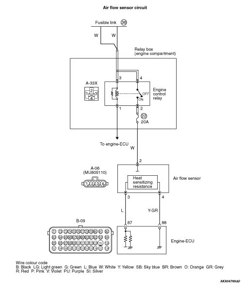
Code No. P0102: Air Flow Sensor Circuit Low Input

OPERATION
- Power is supplied by the engine control relay (terminal
No. 2) to the air flow sensor (terminal No. 2), and the air flow sensor (terminal No. 4) is earthed
through the engine-ECU (terminal No. 88).
- The air flow sensor (terminal No. 3) outputs a sensor signal, which is input into
the engine-ECU (terminal No. 87).
FUNCTION
- The air flow sensor outputs current that varies in accordance
with the intake air volume.
- The engine-ECU uses the amperage output by the air flow sensor and the engine speed
signal in order to determine the basic injection duration of the injector.
TROUBLE JUDGMENT
Check Condition
- More than 3 seconds have passed since the ignition switch was turned to "ON" position.
- Air flow sensor output voltage is less than 0.2 V for 2 seconds.
- None.
PROBABLE CAUSES
- Failed air flow sensor
- Open/short circuit or harness damage in air flow sensor circuit or loose connector
contact
- Failed engine-ECU
DIAGNOSIS PROCEDURE |
STEP 1. M.U.T.-III data list |
|
Q.
Is the check result normal?
|
 Intermittent malfunction (Refer to GROUP 00 - How to Use Troubleshooting/Inspection
Service Points - How to Cope with Intermittent Malfunctions Intermittent malfunction (Refer to GROUP 00 - How to Use Troubleshooting/Inspection
Service Points - How to Cope with Intermittent Malfunctions  ). ). |
|
 Go to Step 2. Go to Step 2. |
|
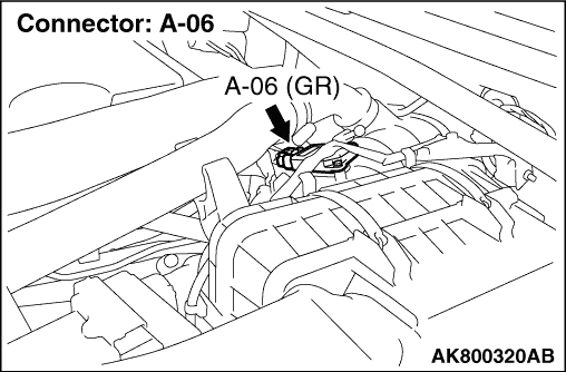
STEP 2. Connector check: A-06 air flow sensor connector |
Q.
Is the check result normal?
|
| Go to Step 3. |
|
| Repair or replace the connector. |
|
STEP 3. Perform voltage measurement at A-06 air flow sensor connector. |
|
| OK: System voltage |
Q.
Is the check result normal?
|
| Go to Step 5. |
|
| Go to Step 4. |
|
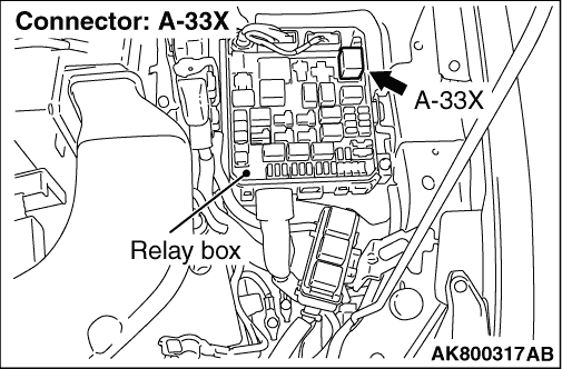
STEP 4. Connector check: A-33X engine control relay connector |
Q.
Is the check result normal?
|
|
|
| Repair or replace the connector. |
|
STEP 5. Connector check: B-09 engine-ECU connector |
Q.
Is the check result normal?
|
| Go to Step 6. |
|
| Repair or replace the connector. |
|
STEP 6. Check harness between A-06 (terminal No. 3) air flow sensor connector and B-09 (terminal No. 87) engine-ECU connector. |
|
Q.
Is the check result normal?
|
| Go to Step 7. |
|
| Repair the damaged harness wire. |
|
STEP 7. Connector check: A-33X engine control relay connector |
Q.
Is the check result normal?
|
| Go to Step 8. |
|
| Repair or replace the connector. |
|
STEP 8. Check harness between A-33X (terminal No. 2) engine control relay connector and A-06 (terminal No. 2) air flow sensor connector. |
|
Q.
Is the check result normal?
|
| Go to Step 9. |
|
| Repair the damaged harness wire. |
|
STEP 9. M.U.T.-III data list |
|
Q.
Is the check result normal?
|
| Intermittent malfunction (Refer to GROUP 00 - How to Use Troubleshooting/Inspection
Service Points - How to Cope with Intermittent Malfunctions ). |
|
| Go to Step 10. |
|
STEP 10. Replace the air flow sensor |
|
Q.
Is the diagnosis code set?
|
| Replace the engine-ECU. |
|
| Check end. |
|