Code No. P0037: Oxygen Sensor (rear) Heater Circuit Low Input


OPERATION


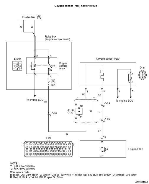
  • Power is supplied to the heater power terminal (terminal No. 1) of the oxygen sensor (rear) connector from the engine control relay (terminal No. 2).
  • The heater (terminal No. 2) of the oxygen sensor (rear) connector is controlled by the power transistor in the engine-ECU (terminal No. 35).

FUNCTION


  • The power supply to the oxygen sensor (rear) heater is controlled by the ON/OFF control of the power transistor in the engine-ECU.
  • Heating the oxygen sensor (rear) heater enables the oxygen sensor (rear) to provide good response even when the exhaust emission temperature is low.

TROUBLE JUDGMENT


Check Conditions
  • Engine is running.
  • Battery positive voltage is more than 11 V and is less than 16.5 V.
Judgement Criterion
  • When the normal operation signal is not output from the heater drive circuit.
FAIL-SAFE AND BACKUP FUNCTION
  • None.

PROBABLE CAUSES


  • Failed oxygen sensor (rear) heater
  • Open/short circuit or harness damage in oxygen sensor (rear) heater circuit or loose connector contact
  • Failed engine-ECU

DIAGNOSIS PROCEDURE


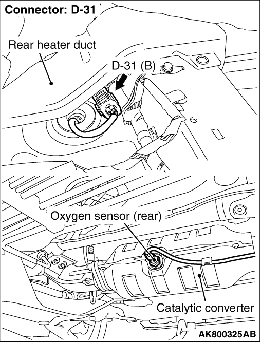
STEP 1. Connector check: D-31 oxygen sensor (rear) connector


Q. Is the check result normal?

Go to Step 2.
Repair or replace the connector.

STEP 2. Perform resistance measurement at D-31 oxygen sensor (rear) connector.


  • Disconnect connector, and measure at sensor side.
  • Resistance between terminal No. 1 and No. 2.
OK: 4.5 - 8.0 Ω (at 20°C)

Q. Is the check result normal?

Go to Step 3.
Replace the oxygen sensor (rear).

STEP 3. Perform voltage measurement at D-31 oxygen sensor (rear) connector.


  • Disconnect connector, and measure at harness side.
  • Ignition switch: ON
  • Voltage between terminal No. 1 and earth.
OK: System voltage

Q. Is the check result normal?

Go to Step 5.
Go to Step 4.

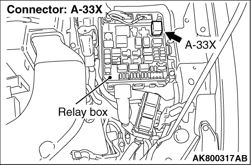
STEP 4. Connector check: A-33X engine control relay connector


Q. Is the check result normal?


    Check intermediate connectors C-31 and C-30 <L.H. drive vehicles> and repair if necessary. If intermediate connectors are normal, check and repair harness between D-31 (terminal No. 1) oxygen sensor (rear) connector and A-33X (terminal No. 2) engine control relay connector.

    • Check power supply line for open/short circuit.
Repair or replace the connector.

STEP 5. Connector check: B-08 engine-ECU connector


Q. Is the check result normal?

Go to Step 6.
Repair or replace the connector.

STEP 6. Perform voltage measurement at B-08 engine-ECU connector.


  • Disconnect connector, and measure at harness side.
  • Ignition switch: ON
  • Voltage between terminal No. 35 and earth.
OK: System voltage

Q. Is the check result normal?

Go to Step 7.

    Check intermediate connectors A-65 and C-29, and repair them if necessary. If intermediate connectors are normal, check and repair harness between D-31 (terminal No. 2) oxygen sensor (rear) connector and B-08 (terminal No. 35) engine-ECU connector.

    • Check earthing line for open/short circuit.

STEP 7. Check harness between D-31 (terminal No. 2) oxygen sensor (rear) connector and B-08 (terminal No. 35) engine-ECU connector.


note Before checking harness, check intermediate connectors A-65 and C-29, and repair them if necessary.

  • Check earthing line for damage.

Q. Is the check result normal?

Go to Step 8.
Repair the damaged harness wire.

STEP 8. Connector check: A-33X engine control relay connector


Q. Is the check result normal?

Go to Step 9.
Repair or replace the connector.

STEP 9. Check harness between D-31 (terminal No. 1) oxygen sensor (rear) connector and A-33X (terminal No. 2) engine control relay connector.


note Before checking harness, check intermediate connectors C-31 and C-30 <L.H. drive vehicles> and repair if necessary.

  • Check power supply line for damage.

Q. Is the check result normal?

Go to Step 10.
Repair the damaged harness wire.

STEP 10. M.U.T.-III diagnosis code


  • Reconfirmation of diagnosis code.

Q. Is diagnosis code set?

Replace the engine-ECU.
Intermittent malfunction (Refer to GROUP 00 - How to Use Troubleshooting/Inspection Service Points - How to Cope with Intermittent Malfunctions ).