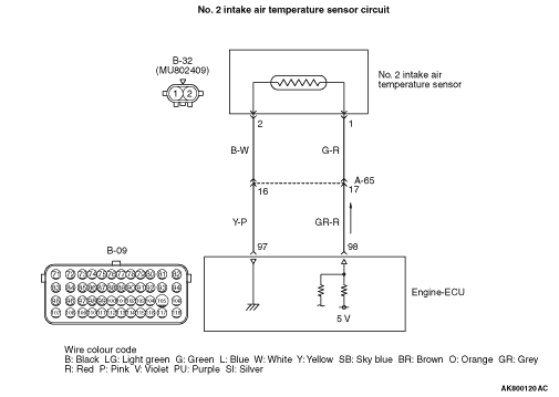
Code No. P0098: No. 2 Intake Air Temperature Sensor Circuit High Input

OPERATION
- A power voltage of 5 V is applied to the No. 2 intake
air temperature sensor output terminal (terminal No. 1) of air flow sensor connector from the
engine-ECU (terminal No. 98).
- The power voltage is earthed to the engine-ECU (terminal No. 97) from the No. 2
intake air temperature sensor (terminal No. 2).
FUNCTION
- The No. 2 intake air temperature sensor converts the
intake air temperature into a voltage and inputs the voltage signal to the engine-ECU.
- In response to the signal, the engine-ECU corrects the fuel injection amount, etc.
- The No. 2 intake air temperature sensor is a kind of resistor, which has characteristics
to reduce its resistance as the intake air temperature rises. Therefore, the sensor output voltage
varies with the intake air temperature, and becomes lower as the intake air temperature rises.
TROUBLE JUDGMENT
Check Condition
- Ignition switch is "ON" position.
- No. 2 intake air temperature sensor output voltage is more than 4.6 V (corresponding
to an intake air temperature of -40°C or less) for 2 seconds.
- Control as if the intake air temperature in the inlet manifold is 25 °C.
PROBABLE CAUSES
- Failed No. 2 intake air temperature sensor
- Open circuit or harness damage in No. 2 intake air temperature sensor circuit or
loose connector contact
- Failed engine-ECU
DIAGNOSIS PROCEDURE |
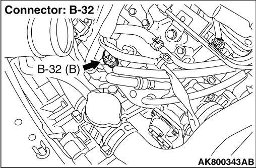
STEP 1. Connector check: B-32 No. 2 intake air temperature sensor connector |
Q.
Is the check result normal?
|
 Go to Step 2. Go to Step 2. |
|
 Repair or replace the connector. Repair or replace the connector. |
|
STEP 2. Check No. 2 intake air temperature sensor itself. |
|
Q.
Is the check result normal?
|
| Go to Step 3. |
|
| Replace the No. 2 intake air temperature sensor. |
|
STEP 3. Perform resistance measurement at B-32 No. 2 intake air temperature sensor connector. |
|
| OK: Continuity (2 Ω or less) |
Q.
Is the check result normal?
|
| Go to Step 7. |
|
| Go to Step 4. |
|
STEP 4. Connector check: B-09 engine-ECU connector |
Q.
Is the check result normal?
|
| Go to Step 5. |
|
| Repair or replace the connector. |
|
STEP 5. Check harness between B-32 (terminal No. 2) No. 2 intake air temperature sensor connector and B-09 (terminal No. 97) engine-ECU connector. |
|
|
Q.
Is the check result normal?
|
| Go to Step 6. |
|
| Repair the damaged harness wire. |
|
STEP 6. M.U.T.-III diagnosis code |
|
Q.
Is diagnosis code set?
|
| Replace the engine-ECU. |
|
Intermittent malfunction (Refer to GROUP 00 - How to Use Troubleshooting/Inspection
Service Points - How to Cope with Intermittent Malfunctions  ). ). |
|
STEP 7. Perform voltage measurement at B-32 No. 2 intake air temperature sensor connector. |
|
| OK: 4.5 - 4.9 V |
Q.
Is the check result normal?
|
| Go to Step 10. |
|
| Go to Step 8. |
|
STEP 8. Connector check: B-09 engine-ECU connector |
Q.
Is the check result normal?
|
|
|
| Repair or replace the connector. |
|
STEP 9. Check harness between B-32 (terminal No. 1) No. 2 intake air temperature sensor connector and B-09 (terminal No. 98) engine-ECU connector. |
|
|
Q.
Is the check result normal?
|
| Go to Step 6. |
|
| Repair the damaged harness wire. |
|
STEP 10. Connector check: B-09 engine-ECU connector |
Q.
Is the check result normal?
|
|
|
| Repair or replace the connector. |
|
STEP 11. Check harness between B-32 (terminal No. 1) No. 2 intake air temperature sensor connector and B-09 (terminal No. 98) engine-ECU connector. |
|
|
Q.
Is the check result normal?
|
| Go to Step 6. |
|
| Repair the damaged harness wire. |
|