Code No. P0132: Oxygen Sensor (front) Circuit High Voltage

OPERATION
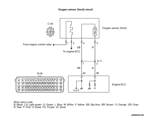
- The sensor signal is inputted to the engine-ECU (terminal
No. 38) from the oxygen sensor (front) output terminal (terminal No. 3).
- The oxygen sensor (front) (terminal No. 4) is earthed with engine-ECU (terminal
No. 39).
- The engine-ECU (terminal No. 39) applies an offset voltage of 0.5 V to the oxygen
sensor (front) (terminal No. 4).
FUNCTION
- The oxygen sensor (front) converts the concentration
of oxygen in the exhaust emission into a voltage and inputs the signal to the engine-ECU.
- When the air-fuel ratio is richer than the theoretical air-fuel ratio, the oxygen
sensor (front) outputs a voltage of about 1 V. When it is leaner than the theoretical air-fuel
ratio, it outputs a voltage of about 0 V.
- In response to the signal, the engine-ECU controls the fuel injection amount so
that the air-fuel ratio can be equivalent to the theoretical air-fuel ratio.
TROUBLE JUDGMENT
Check Conditions
- Oxygen sensor (front) offset voltage is more than 0.4 V and is less than 0.6 V.
- More than 2 seconds have passed since the engine starting sequence was completed.
- Oxygen sensor (front) output voltage is more than 1.8 V for 2 seconds.
FAIL-SAFE AND BACKUP FUNCTION
- None
PROBABLE CAUSES
- Short circuit in oxygen sensor (front) circuit or loose
connector contact
- Failed engine-ECU
DIAGNOSIS PROCEDURE |
STEP 1. M.U.T.-III data list |
|
Q.
Are the check results normal?
|
 Intermittent malfunction (Refer to GROUP 00 - How to Use Troubleshooting/Inspection
Service Points - How to Cope with Intermittent Malfunctions Intermittent malfunction (Refer to GROUP 00 - How to Use Troubleshooting/Inspection
Service Points - How to Cope with Intermittent Malfunctions  ). ). |
|
 Go to Step 2 . Go to Step 2 . |
|
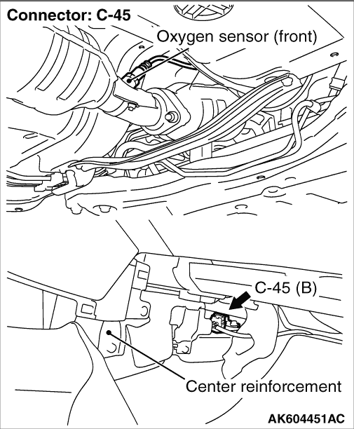
STEP 2. Connector check: B-08 engine-ECU connector and C-45 oxygen sensor (front) connector |
Q.
Are the check results normal?
|
| Go to Step 3 . |
|
| Repair or replace the connector. |
|
STEP 3. Check harness between C-45 (terminal No. 3) oxygen sensor (front) connector and B-08 (terminal No. 38) engine-ECU connector. |
|
|
Q.
Is the check result normal?
|
| Go to Step 4 . |
|
| Repair the damaged harness wire. |
|
STEP 4. Check harness between C-45 (terminal No. 4) oxygen sensor (front) connector and B-08 (terminal No. 39) engine-ECU connector. |
|
|
Q.
Is the check result normal?
|
| Go to Step 5 . |
|
| Repair the damaged harness wire. |
|
STEP 5. M.U.T.-III data list |
|
Q.
Is the check result normal?
|
| Intermittent malfunction (Refer to GROUP 00 - How to Use Troubleshooting/Inspection
Service Points - How to Cope with Intermittent Malfunctions ). |
|
| Replace the engine-ECU. |
|