Item No.
|
Item name
|
Unit
|
4
|
Accumulated minute timer
|
min
|
17
|
Current error type
|
-
|
21
|
Engine coolant temperature sensor
|
°C
|
23
|
Engine speed
|
r/min
|
24
|
DTC read counter
|
Times
|
46
|
Error type debounced
|
-
|
54
|
Frequency counter
|
Times
|
55
|
Target boost pressure
|
hPa
|
59
|
Ignition cycle counter
|
Times
|
64
|
Mileage at last occurrence
|
km
|
102
|
Brake switch (Stop lamp switch)
|
-
|
171
|
Boost pressure sensor
|
hPa
|
245
|
A/C selected
|
-
|
246
|
Accelerator pedal (main)
|
%
|
247
|
Accelerator pedal (sub)
|
%
|
248
|
Ambient air temperature from CAN
|
°C
|
251
|
Clutch interlock switch
|
-
|
252
|
Clutch upstop switch
|
-
|
254
|
Cruise control governor active not OFF
|
-
|
255
|
Driver overrides active cruise control
|
-
|
256
|
Driver requested engine torque
|
N·m
|
257
|
EGR output
|
%
|
259
|
Main switch cruise indicator
|
-
|
260
|
Mass air flow actual
|
kg/h air
|
261
|
Redundant brake switch
|
-
|
262
|
Static engine torque
|
N·m
|
265
|
Ignition switch (IG1)
|
-
|
266
|
Vehicle speed from CAN
|
km/h
|
272
|
Dutycycle below allowed minimum
|
-
|
276
|
Can signal - vehicle speed invalid
|
-
|
277
|
Air mass ratio (threshold high)
|
-
|
278
|
Air mass ratio (threshold low)
|
-
|
279
|
Beginning of injection period of solenoid valve (No.
1 cylinder below limit)
|
-
|
280
|
Beginning of injection period of solenoid valve (No.
2 cylinder below limit)
|
-
|
281
|
Beginning of injection period of solenoid valve (No.
3 cylinder below limit)
|
-
|
282
|
Beginning of injection period of solenoid valve (No.
4 cylinder below limit)
|
-
|
283
|
Variable geometry position sensor fault
|
-
|
287
|
Configuration not valid
|
-
|
288
|
Data variant not valid
|
-
|
289
|
Default value used
|
-
|
290
|
Deviation (accelerator pedal position sensor main/sub)
voltage high
|
-
|
291
|
Differential pressure signal
|
-
|
292
|
Engine control mode not plausible
|
-
|
293
|
Engine oil pressure too low
|
-
|
295
|
Last read operation error
|
-
|
296
|
Last write operation error
|
-
|
297
|
Plausibility error signal of ignition switch-IG
|
-
|
298
|
Error path jammed valve for EGR
|
-
|
299
|
Error path of drift error
|
-
|
300
|
EGR valve position sensor error
|
-
|
301
|
No. 1 exhaust gas temperature sensor error
|
-
|
302
|
Throttle position sensor error
|
-
|
303
|
Engine-ECU not written (code word)
|
-
|
304
|
VIN writing incompleted
|
-
|
306
|
Excess temperature
|
-
|
307
|
Exhaust gas temperature after DPF monitor
|
-
|
308
|
Fast decay error
|
-
|
309
|
Decay error (cylinder)/short circuit to earth
|
-
|
310
|
No load/excess temperature (swirl control solenoid valve)
|
-
|
311
|
Short circuit to battery (swirl control solenoid valve)
|
-
|
312
|
Short circuit to earth (swirl control solenoid valve)
|
-
|
313
|
Oxygen concentration error
|
-
|
314
|
Bus off Bus 1
|
-
|
317
|
Error (intake manifold)
|
-
|
318
|
Fault path to CAN message A/C
|
-
|
319
|
Fault path to CAN message ABS/ASC
|
-
|
320
|
Diagnosis transmission/protocol error
|
-
|
321
|
Exhaust gas temperature pre turbine monitoring
|
-
|
322
|
Flow resistance monitoring
|
-
|
323
|
Fuel temperature sensor signal implausibility
|
-
|
324
|
Function code not valid
|
-
|
325
|
Glow plug defect/not connect
|
-
|
326
|
Hose line defective
|
-
|
327
|
Hardware signal (vehicle speed) invalid
|
-
|
329
|
Jammed valve detection
|
-
|
330
|
Engine control relay does not open in time
|
-
|
331
|
Engine control relay opens too early
|
-
|
332
|
Minimum temperature/temperature no reached
|
-
|
333
|
Air/fuel ratio sensor heater power stage
|
-
|
334
|
Air/fuel ratio sensor nernst cell pin
|
-
|
335
|
Air/fuel ratio sensor oxygen voltage calibration value
|
-
|
336
|
Air/fuel ratio sensor pump current pin
|
-
|
337
|
Air/fuel ratio sensor virtual ground pin
|
-
|
338
|
Negative governor deviation below limit
|
-
|
339
|
No crankshaft signal
|
-
|
340
|
No load
|
-
|
341
|
Not plausible fault
|
-
|
342
|
Barometric pressure sensor implausibility
|
-
|
343
|
Recognized misfire (above limit)
|
-
|
344
|
Offset (camshaft/crankshaft)
|
-
|
345
|
Engine oil pressure switch position not plausible
|
-
|
346
|
Exhaust differential pressure sensor
|
-
|
347
|
No. 3 exhaust gas temperature sensor
|
-
|
348
|
No. 2 exhaust gas temperature sensor
|
-
|
349
|
DPF regeneration strategy fail
|
-
|
350
|
Plausibility check (No. 1 exhaust gas temperature sensor)
|
-
|
352
|
Positive governor deviation above limit
|
-
|
353
|
Ri value monitor of air/fuel ratio sensor
|
-
|
354
|
Exhaust gas temperature pre DPF monitoring
|
-
|
355
|
Short circuit to battery
|
-
|
356
|
Short circuit to earth
|
-
|
357
|
Short circuit on lower stop to battery
|
-
|
358
|
Short circuit/over current
|
-
|
359
|
Short circuit to battery
|
-
|
361
|
Signal error only in case of CAN
|
-
|
362
|
Vehicle speed invalid injection mass/engine speed
|
-
|
363
|
Vehicle speed invalid overrun
|
-
|
367
|
Line error
|
-
|
368
|
Line error (initialise failed)
|
-
|
370
|
Solenoid valve (No. 1 cylinder) exceed max negative
deviation
|
-
|
371
|
Solenoid valve (No. 1 cylinder) exceed max positive
deviation
|
-
|
372
|
Solenoid valve (No. 2 cylinder) exceed max negative
deviation
|
-
|
373
|
Solenoid valve (No. 2 cylinder) exceed max positive
deviation
|
-
|
374
|
Solenoid valve (No. 3 cylinder) exceed max negative
deviation
|
-
|
375
|
Solenoid valve (No. 3 cylinder) exceed max positive
deviation
|
-
|
376
|
Solenoid valve (No. 4 cylinder) exceed max negative
deviation
|
-
|
377
|
Solenoid valve (No. 4 cylinder) exceed max positive
deviation
|
-
|
378
|
Supply voltage missing
|
-
|
379
|
Adaptive cruise control permanent high
|
-
|
380
|
Voltage above upper limit
|
-
|
381
|
Voltage below lower limit
|
-
|
382
|
Wrong crank angle sensor signal
|
-
|
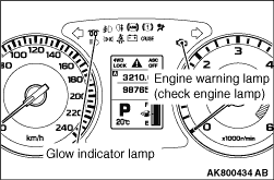
 , Inspection Chart For Diagnosis Code.