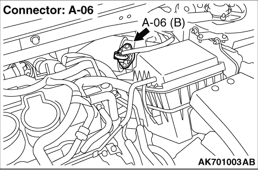
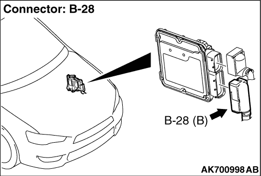
|
|
Q.
Is the check result normal?
|
|
|
 Repair or replace the connector. Repair or replace the connector.
|
|
|
|
|
|
- Disconnect connector, and measure at the harness side.
- Ignition switch: ON
- Voltage between terminal No. 2 and earth.
|
|
|
Q.
Is the check result normal?
|
|
|
Q.
Is the check result normal?
|
|
|

Check intermediate connector C-128, and repair
if necessary. If intermediate connector is normal, check harness between the C-317 (terminal
No. 5) ETACS-ECU connector and A-06 (terminal No. 2) air flow sensor connector.
- Check power supply line for open/short circuit.
|
|
|
|
|
|
Repair or replace the connector.
|
|
|
|
|
|
- Disconnect connector, and measure at the harness side.
- Resistance between terminal No. 3 and earth.
|
|
|
OK: Continuity (2 Ω or less)
|
|
|
Q.
Is the check result normal?
|
|
|
Q.
Is the check result normal?
|
|
|
Check harness between the A-06 (terminal No.
3) air flow sensor connector and B-28 (terminal No. 98) engine-ECU connector.
- Check earthing line for open circuit and damage.
|
|
|
|
|
|
Repair or replace the connector.
|
|
|
|
|
|
- Disconnect connector, and measure at the harness side.
- Ignition switch: ON
- Voltage between terminal No. 4 and earth.
|
|
|
Q.
Is the check result normal?
|
|
|
Q.
Is the check result normal?
|
|
|
Repair or replace the connector.
|
|
|
|
|
|
- Check power supply line for open/short circuit.
|
|
|
Q.
Is the check result normal?
|
|
|
Repair the damaged harness wire.
|
|
|
|
|
|
Q.
Does trouble symptom persist?
|
|
|
Intermittent malfunction (Refer to GROUP 00 - How to Use Troubleshooting/Inspection
Service Points - How to Cope with Intermittent Malfunctions  ). ).
|
|
|
|
|
|
- Check power supply line for damage.
|
|
|
Q.
Is the check result normal?
|
|
|
Repair the damaged harness wire.
|
|
|
|
|
|
- Check output line for damage.
|
|
|
Q.
Is the check result normal?
|
|
|
Repair the damaged harness wire.
|
|
|
|
|
|
- Check output line for open/short circuit and damage.
|
|
|
Q.
Is the check result normal?
|
|
|
Repair the damaged harness wire.
|
|
|
|
|
|
- After replacing the air flow sensor, re-check the trouble symptoms.
|
|
|
Q.
Does trouble symptom persist?
|