Inspection Procedure 19: EGR Valve (DC Motor) System


OPERATION
- The electric current from the engine-ECU (terminal No. 4 and No. 5) to the EGR
valve (DC motor) (terminal No. 3 and No. 1) is controlled.
FUNCTION
- Engine-ECU changes current direction according to the Open/Close direction
and also changes current to the motor coil in order to the control EGR valve.
- The engine-ECU performs feedback control over the EGR valve based on the signals
from the EGR valve position sensor.
PROBABLE CAUSES
- Failed EGR valve
- Open/short circuit or harness damage in EGR valve circuit or loose connector contact
- Failed engine-ECU
DIAGNOSIS PROCEDURE |
STEP 1. Connector check: B-30-1 EGR valve connector |
Q.
Is the check result normal?
|
 Go to Step 2 . Go to Step 2 . |
|
 Repair or replace the connector. Repair or replace the connector. |
|
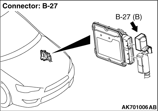
STEP 2. Connector check: B-27 engine-ECU connector |
Q.
Is the check result normal?
|
| Go to Step 3 . |
|
| Repair or replace the connector. |
|
STEP 3. Check harness between the B-27 (terminal No. 4) engine-ECU connector and B-30-1 (terminal No. 3) EGR valve connector. |
|
|
Q.
Is the check result normal?
|
| Go to Step 4 . |
|
| Repair the damaged harness wire. |
|
STEP 4. Check harness between B-27 (terminal No. 5) engine-ECU connector and B-30-1 (terminal No. 1) EGR valve connector. |
|
|
Q.
Is the check result normal?
|
| Go to Step 5 . |
|
| Repair the damaged harness wire. |
|
STEP 5. Replace the EGR valve assembly. |
|
Q.
Does trouble symptom persist?
|
| Replace the engine-ECU. |
|
| The check is end. |
|