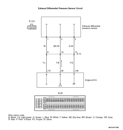
Inspection Procedure 33: Exhaust Differential Pressure Sensor System <Vehicle with DPF>
OPERATION
- A power voltage of 5 V is applied to the exhaust differential
pressure sensor power terminal (terminal No. 3) from the engine-ECU (terminal No. 96) and earthed
to the engine-ECU (terminal No. 138) from the exhaust differential pressure sensor (terminal
No. 2).
- The sensor signal is inputted to the engine-ECU (terminal No. 137) from the exhaust
differential pressure sensor output terminal (terminal No. 1).
FUNCTION
- The exhaust differential pressure sensor outputs the
voltage to the engine-ECU in accordance with the difference in the voltage between the DPF upstream
area and the DPF downstream area.
- The engine-ECU anticipates the amount of PM accumulated in the DPF through this
output voltage.
PROBABLE CAUSES
- Failed exhaust differential pressure sensor
- Open/short circuit or harness damage in exhaust differential pressure sensor circuit
or loose connector contact
- Failed engine-ECU
DIAGNOSIS PROCEDURE |
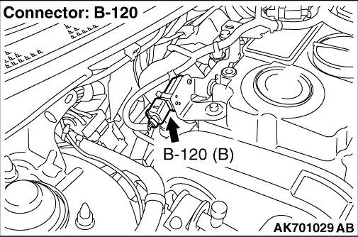
STEP 1. Connector check: B-120 exhaust differential pressure sensor connector |
Q.
Is the check result normal?
|
 Go to Step 2 . Go to Step 2 . |
|
 Repair or replace the connector. Repair or replace the connector. |
|
STEP 2. Perform voltage measurement at B-120 exhaust differential pressure sensor connector. |
|
| OK: 4.9 - 5.1 V |
Q.
Is the check result normal?
|
| Go to Step 8 . |
|
| Go to Step 3 . |
|
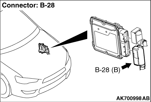
STEP 3. Perform voltage measurement at B-28 engine-ECU connector. |
|
| OK: 4.9 - 5.1 V |
Q.
Is the check result normal?
|
| Go to Step 4 . |
|
| Go to Step 5 . |
|
STEP 4. Connector check: B-28 engine-ECU connector |
Q.
Is the check result normal?
|
|
|
| Repair or replace the connector. |
|
STEP 5. Connector check: B-28 engine-ECU connector |
Q.
Is the check result normal?
|
| Go to Step 6 . |
|
| Repair or replace the connector. |
|
STEP 6. Check harness between B-120 (terminal No. 3) exhaust differential pressure sensor connector and B-28 (terminal No. 96) engine-ECU connector. |
|
|
Q.
Is the check result normal?
|
| Go to Step 7 . |
|
| Repair the damaged harness wire. |
|
STEP 7. Check the trouble symptoms. |
Q.
Does trouble symptom persist?
|
| Replace the engine-ECU. |
|
Intermittent malfunction (Refer to GROUP 00 - How to Use Troubleshooting/Inspection
Service Points - How to Cope with Intermittent Malfunctions  ). ). |
|
STEP 8. Perform resistance measurement at B-120 exhaust differential pressure sensor connector. |
|
| OK: Continuity (2 Ω or less) |
Q.
Is the check result normal?
|
| Go to Step 11 . |
|
| Go to Step 9 . |
|
STEP 9. Connector check: B-28 engine-ECU connector |
Q.
Is the check result normal?
|
| Go to Step 10 . |
|
| Repair or replace the connector. |
|
STEP 10. Check harness between B-120 (terminal No. 2) exhaust differential pressure sensor connector and B-28 (terminal No. 138) engine-ECU connector. |
|
|
Q.
Is the check result normal?
|
| Go to Step 7 . |
|
| Repair the damaged harness wire. |
|
STEP 11. Connector check: B-28 engine-ECU connector |
Q.
Is the check result normal?
|
| Go to Step 12 . |
|
| Repair or replace the connector. |
|
STEP 12. Check harness between B-120 (terminal No. 3) exhaust differential pressure sensor connector and B-28 (terminal No. 96) engine-ECU connector. |
|
|
Q.
Is the check result normal?
|
| Go to Step 13 . |
|
| Repair the damaged harness wire. |
|
STEP 13. Check harness between B-120 (terminal No. 1) exhaust differential pressure sensor connector and B-28 (terminal No. 137) engine-ECU connector. |
|
|
Q.
Is the check result normal?
|
| Go to Step 14 . |
|
| Repair the damaged harness wire. |
|
STEP 14. Replace the exhaust differential pressure sensor. |
|
Q.
Does trouble symptom persist?
|
| Replace the engine-ECU. |
|
| The check is end. |
|