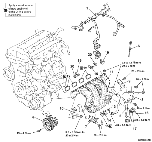
REMOVAL AND INSTALLATION <4B10>


Pre-removal operation
  • Engine Coolant Draining (Refer to GROUP 14 - On-vehicle Service, Engine Coolant Replacement ).
  • Engine Upper Cover Removal (Refer to GROUP 11C - Camshaft ).
  • Alternator and Others Belt Removal (Refer to GROUP 11C - Crankshaft Pulley ).
  • Air Cleaner Intake Hose and Air Cleaner Assembly Removal (Refer to ).
  • Throttle Body Assembly Removal (Refer to GROUP 13B - Throttle Body Assembly ).
  • Fuel Injector Removal (Refer to GROUP 13B - Injector ).

Post-installation operation
  • Fuel Injector Installation (Refer to GROUP 13B - Injector ).
  • Throttle Body Assembly Installation (Refer to GROUP 13B - Throttle Body Assembly ).
  • Air Cleaner Intake Hose and Air Cleaner Assembly Installation (Refer to ).
  • Alternator and Others Belt Installation (Refer to GROUP 11C - Crankshaft Pulley ).
  • Engine Upper Cover Installation (Refer to GROUP 11C - Camshaft ).
  • Engine Coolant Refilling (Refer to GROUP 14 - On-vehicle Service, Engine Coolant Replacement ).


Removal steps


1.
Control wiring harness connection


2.
Emission vacuum hose


3.
Brake booster vacuum hose
<<A>>

4.
Power steering oil pump assembly


5.
Rocker cover PCV hose


6.
Engine oil level gauge


7.
Inlet manifold stay


8.
Inlet manifold stay B


9.
Inlet manifold stay C

>>C<<
10.
Injector protector front

>>C<<
11.
Inlet manifold assembly


12.
Inlet manifold gasket

>>A<<
13.
Screw

>>B<<
14.
Manifold absolute pressure sensor


15.
O-ring

>>A<<
16.
Screw


17.
Purge control solenoid valve


18.
O-ring


19.
Inlet manifold harness bracket


20.
Engine cover bracket

REMOVAL SERVICE POINT


<<A>> POWER STEERING OIL PUMP ASSEMBLY REMOVAL


1.With the hose installed, remove the power steering oil pump assembly from the bracket.
2.Tie the removed power steering oil pump assembly with a string at a position where it will not interfere with the removal and installation of the inlet manifold.

INSTALLATION SERVICE POINTS


>>A<< SCREW INSTALLATION


caution Do not over-tighten. As the self-forming-type screw is used, the excessive torque can damage the inlet manifold threads.

>>B<< MANIFOLD ABSOLUTE PRESSURE SENSOR INSTALLATION


caution
  • Install the manifold absolute pressure sensor, taking care not to give a shock to it.
  • Do not use a manifold absolute pressure sensor that has fallen down.

>>C<< INLET MANIFOLD ASSEMBLY/INJECTOR PROTECTOR FRONT INSTALLATION


Install the inlet manifold assembly and the injector protector front, and tighten mounting bolts and nuts temporarily.
note The tightening of the delivery pipe assembly, the inlet manifold assembly and the injector protector front has the specified order. Temporarily tighten the inlet manifold assembly and injector protector front mounting bolts and nuts (Refer to GROUP 13B - Injector ).