Code No.P0578: Cruise Control Switch Stuck
Code No.P0579: Cruise Control Switch Range
Code No.P0580: Cruise Control Switch Low
Code No.P0581: Cruise Control Switch High
Code No.P0591, P0592, P0593: Cruise Control Component Driver Key Signal 2
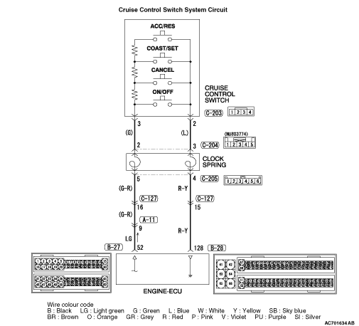
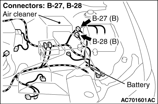
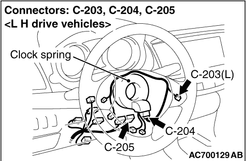
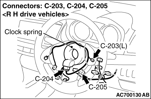
OPERATION
- When all switches are OFF: 4.7 - 5.0 volts
- When the "ON/OFF" switch is ON: 0 - 0.5 volt
- When the "CANCEL" switch is ON: 1.0 - 1.8 volts
- When the "COAST/SET" switch is ON: 2.3 - 3.0 volts
- When the "ACC/RES" switch is ON: 3.5 - 4.2 volts
DIAGNOSIS CODE SET CONDITIONS
- If the cruise control switch is operated, this diagnosis code will be set when the engine-ECU terminal voltage is different from the standard value.
- Or, this code is set when the "COAST/SET" switch or "ACC/RES" switch is stuck to ON.
POSSIBLE CAUSES
- Damaged harness or connector.
- Malfunction of the cruise control switch.
- Malfunction of the clock spring.
- Malfunction of the engine-ECU.
|
|
STEP 1. Check the data list.
|
|
|
Using M.U.T.-III, check the data list (Refer to  - data list reference table). - data list reference table).
|
|
|
- Item 285: Cruise control switch
|
|
|
Q.
Is the check result normal?
|
|
|
 Go to Step 20. Go to Step 20.
|
|
|
|
|
|
 Go to Step 2. Go to Step 2.
|
|
|
|
|
|
STEP 2. Measure the voltage at cruise control switch connector C-203.
|
|
|
(1)Remove the driver’s air bag module (Refer to GROUP 52B - Driver’s Air Bag Module and Clock Spring <Except for RALLIART> ).
|
|
|
(2)Remove the cruise control switch from the steering wheel with the cruise control switch connector connected (Refer to ).
|
|
|
(3)Connect the negative battery cable that was disconnected when the driver’s air bag module was removed.
|
|
|
(4)Turn the ignition switch to the "ON" position.
|
|
|
(5)Do not operate the cruise control switch.
|
|
|
(6)Measure the terminal voltage between cruise control switch connector C-203 terminal No.3 and earth with cruise control switch connector C-203 connected.
OK: 4.7 - 5.0 V
|
|
|
(7)Turn the ignition switch to the "LOCK" (OFF) position.
|
|
|
(8)Install the cruise control switch to the steering wheel (Refer to ).
|
|
|
Q.
Is the check result normal?
|
|
|
Go to Step 10.
|
|
|
|
|
|
Go to Step 3.
|
|
|
|
|
|
STEP 3. Measure the terminal voltage at engine-ECU connector B-27.
|
|
|
(1)Remove the engine-ECU (Refer to GROUP 13D - Engine-ECU ).
|
|
|
(2)Connect special tool power plant ECU check harness (MB992044) between the engine-ECU and the body-side harness connector.
|
|
|
(3)Turn the ignition switch to the "ON" position.
|
|
|
(4)Do not operate the cruise control switch.
|
|
|
(5)Measure the terminal voltage between special tool 60-pin connector terminal No.52 (engine-ECU connector B-27 terminal No.52) and earth.
OK: 4.7 - 5.0 V
|
|
|
(6)Turn the ignition switch to the "LOCK" (OFF) position.
|
|
|
(7)Disconnect special tool MB992044 between the engine-ECU and the body-side harness connector.
|
|
|
(8)Install the engine-ECU (Refer to GROUP 13D - Engine-ECU ).
|
|
|
Q.
Is the check result normal?
|
|
|
Go to Step 6.
|
|
|
|
|
|
Go to Step 4.
|
|
|
|
|
|
STEP 4. Connector check: B-27 engine-ECU connector.
|
|
|
Q.
Is the check result normal?
|
|
|
Go to Step 5.
|
|
|
|
|
|
Repair or replace the damaged connector. Install the driver’s air bag module (Refer to GROUP 52B - Driver’s Air Bag Module and Clock Spring <Except for RALLIART> ). Then go to Step 21.
|
|
|
|
|
|
STEP 5. Check the harness for short circuit to earth between engine-ECU connector B-27 terminal No.52 and the cruise control switch connector C-203 terminal No.3.
|
|
|
(1)Disconnect engine-ECU connector B-27 and measure at the harness connector side.
|
|
|
(2)Turn the ignition switch to the "LOCK" (OFF) position.
|
|
|
(3)Measure the continuity between engine-ECU connector B-27 terminal No.52 and earth.
|
|
|
(4)Connect engine-ECU connector B-27.
|
|
|
Q.
Is the measured continuity open circuit?
|
|
|
Install the driver’s air bag module (Refer to GROUP 52B - Driver’s Air Bag Module and Clock Spring <Except for RALLIART> ). Then go to Step 19.
|
|
|
|
|
|
Go to Step 6.
|
|
|
|
|
|
STEP 6. Connectors check: C-203 cruise control switch connector, C-204 and C-205 clock spring connectors, A-11 and C-127 intermediate connectors.
|
|
|
Q.
Is the check result normal?
|
|
|
Go to Step 7.
|
|
|
|
|
|
Repair or replace the damaged connector. Install the driver’s air bag module (Refer to GROUP 52B - Driver’s Air Bag Module and Clock Spring <Except for RALLIART> ). Then go to Step 21.
|
|
|
|
|
|
STEP 7. Check the harness wire between engine-ECU connector B-27 terminal No.52 and the cruise control switch connector C-203 terminal No.3.
|
|
|
Q.
Is the check result normal?
|
|
|
Go to Step 8.
|
|
|
|
|
|
Repair the damaged harness wire. Install the driver’s air bag module (Refer to GROUP 52B - Driver’s Air Bag Module and Clock Spring <Except for RALLIART> ). Then go to Step 21.
|
|
|
|
|
|
STEP 8. Check the clock spring.
|
|
|
Refer to GROUP 52B - Driver’s Air Bag Module Inspection <Except for RALLIART> .
|
|
|
Q.
Is the check result normal?
|
|
|
Go to Step 9.
|
|
|
|
|
|
Replace the clock spring and install the driver’s air bag module (Refer to GROUP 52B - Driver’s Air Bag Module and Clock Spring <Except for RALLIART> ). Then go to Step 21.
|
|
|
|
|
|
STEP 9. Check the data list.
|
|
|
Using M.U.T.-III, check the data list (Refer to - data list reference table).
|
|
|
- Item 285: Cruise control switch
|
|
|
Q.
Is the check result normal?
|
|
|
It can be assumed that this malfunction is intermittent (Refer to GROUP 00 - How to Use Troubleshooting/Inspection Service Points, How to Cope with Intermittent Malfunction ). Install the driver’s air bag module (Refer to GROUP 52B - Driver’s Air Bag Module and Clock Spring <Except for RALLIART> ).
|
|
|
|
|
|
Return to Step 2.
|
|
|
|
|
|
STEP 10. Measure the voltage at cruise control switch connector C-203.
|
|
|
(1)Remove the cruise control switch from the steering wheel with the cruise control switch connector connected (Refer to ).
|
|
|
(2)Turn the ignition switch to the "ON" position.
|
|
|
(3)Press the "ON/OFF" switch with cruise control switch connector C-203 connected, and measure the terminal voltage between cruise control switch connector C-203 terminal No.2 and earth.
OK: 0.5 V or less
|
|
|
(4)Release the "ON/OFF" switch.
|
|
|
(5)Turn the ignition switch to the "LOCK" (OFF) position.
|
|
|
(6)Install the cruise control switch to the steering wheel (Refer to ).
|
|
|
Q.
Is the check result normal?
|
|
|
Go to Step 17.
|
|
|
|
|
|
Go to Step 11.
|
|
|
|
|
|
STEP 11. Measure the terminal voltage at engine-ECU connector B-28.
|
|
|
(1)Remove the engine-ECU (Refer to GROUP 13D - Engine-ECU ).
|
|
|
(2)Connect special tool power plant ECU check harness (MB992044) between the engine-ECU and the body-side harness connector.
|
|
|
(3)Turn the ignition switch to the "ON" position.
|
|
|
(4)Press the "ON/OFF" switch, and measure the voltage between special tool 94-pin connector terminal No.128 (engine-ECU connector B-28 terminal No.128) and earth.
OK: 0.5 V or less
|
|
|
(5)Release the "ON/OFF" switch.
|
|
|
(6)Turn the ignition switch to the "LOCK" (OFF) position.
|
|
|
(7)Disconnect special tool MB992044 between the engine-ECU and the body-side harness connector.
|
|
|
(8)Install the engine-ECU (Refer to GROUP 13D - Engine-ECU ).
|
|
|
Q.
Is the check result normal?
|
|
|
Go to Step 13.
|
|
|
|
|
|
Go to Step 12.
|
|
|
|
|
|
STEP 12. Connector check: B-28 engine-ECU connector.
|
|
|
Q.
Is the check result normal?
|
|
|
Install the driver’s air bag module (Refer to GROUP 52B - Driver’s Air Bag Module and Clock Spring <Except for RALLIART> ). Then go to Step 19.
|
|
|
|
|
|
Repair or replace the damaged connector. Install the driver’s air bag module (Refer to GROUP 52B - Driver’s Air Bag Module and Clock Spring <Except for RALLIART> ). Then go to Step 21.
|
|
|
|
|
|
STEP 13. Connectors check: B-28 engine-ECU connector, C-203 cruise control switch connector, C-204 and C-205 clock spring connectors, A-11 and C-127 intermediate connectors.
|
|
|
Q.
Is the check result normal?
|
|
|
Go to Step 14.
|
|
|
|
|
|
Repair or replace the damaged connector. Install the driver’s air bag module (Refer to GROUP 52B - Driver’s Air Bag Module and Clock Spring <Except for RALLIART> ). Then go to Step 21.
|
|
|
|
|
|
STEP 14. Check the harness wire between engine-ECU connector B-28 terminal No.128 and the cruise control switch connector C-203 terminal No.2.
|
|
|
Q.
Is the check result normal?
|
|
|
Go to Step 15.
|
|
|
|
|
|
Repair the damaged harness wire. Install the driver’s air bag module (Refer to GROUP 52B - Driver’s Air Bag Module and Clock Spring <Except for RALLIART> ). Then go to Step 21.
|
|
|
|
|
|
STEP 15. Check the clock spring.
|
|
|
Refer to GROUP 52B - Driver’s Air Bag Module Inspection <Except for RALLIART> .
|
|
|
Q.
Is the check result normal?
|
|
|
Go to Step 16.
|
|
|
|
|
|
Replace the clock spring and install the driver’s air bag module (Refer to GROUP 52B - Driver’s Air Bag Module and Clock Spring <Except for RALLIART> ). Then go to Step 21.
|
|
|
|
|
|
STEP 16. Check the data list.
|
|
|
Using M.U.T.-III, check the data list (Refer to - data list reference table).
|
|
|
- Item 285: Cruise control switch
|
|
|
Q.
Is the check result normal?
|
|
|
It can be assumed that this malfunction is intermittent (Refer to GROUP 00 - How to Use Troubleshooting/Inspection Service Points, How to Cope with Intermittent Malfunction ). Install the driver’s air bag module (Refer to GROUP 52B - Driver’s Air Bag Module and Clock Spring <Except for RALLIART> ).
|
|
|
|
|
|
Return to Step 2.
|
|
|
|
|
|
STEP 17. Connector check: C-203 cruise control switch connector.
|
|
|
Q.
Is the check result normal?
|
|
|
Go to Step 18.
|
|
|
|
|
|
Repair or replace the damaged connector. Install the driver’s air bag module (Refer to GROUP 52B - Driver’s Air Bag Module and Clock Spring <Except for RALLIART> ). Then go to Step 21.
|
|
|
|
|
|
STEP 18. Check the cruise control switch.
|
|
|
Refer to .
|
|
|
Q.
Is the check result normal?
|
|
|
Install the driver’s air bag module (Refer to GROUP 52B - Driver’s Air Bag Module and Clock Spring <Except for RALLIART> ). Then go to Step 19.
|
|
|
|
|
|
Replace the cruise control switch (Refer to ). Install the driver’s air bag module (Refer to GROUP 52B - Driver’s Air Bag Module and Clock Spring <Except for RALLIART> ). Then go to Step 21.
|
|
|
|
|
|
STEP 19. Check the data list.
|
|
|
Using M.U.T.-III, check the data list (Refer to - data list reference table).
|
|
|
- Item 285: Cruise control switch
|
|
|
Q.
Is the check result normal?
|
|
|
Go to Step 20.
|
|
|
|
|
|
Replace the engine-ECU (Refer to GROUP 13D - Engine-ECU ). When the Engine-ECU is replaced, register the encrypted code (Refer to GROUP 42C - Troubleshooting, ID Code Registration Necessity Judgment Table ). Then go to Step 21.
|
|
|
|
|
|
STEP 20. Read the diagnosis code.
|
|
|
Using M.U.T.-III, read the diagnosis code of the cruise control system (Refer to ).
|
|
|
Q.
Is diagnosis code No.P0578, P0579, P0580, P0581, P0591, P0592 or P0593 set?
|
|
|
Replace the engine-ECU (Refer to GROUP 13D - Engine-ECU ). When the Engine-ECU is replaced, register the encrypted code (Refer to GROUP 42C - Troubleshooting, ID Code Registration Necessity Judgment Table ). Then go to Step 21.
|
|
|
|
|
|
It can be assumed that this malfunction is intermittent (Refer to GROUP 00 - How to Use Troubleshooting/Inspection Service Points, How to Cope with Intermittent Malfunction ).
|
|
|
|
|
|
STEP 21. Check the data list.
|
|
|
Using M.U.T.-III, check the data list (Refer to - data list reference table).
|
|
|
- Item 285: Cruise control switch
|
|
|
Q.
Is the check result normal?
|
|
|
Go to Step 22.
|
|
|
|
|
|
Return to Step 2.
|
|
|
|
|
|
STEP 22. Read the diagnosis code.
|
|
|
Using M.U.T.-III, read the diagnosis code of the cruise control system (Refer to ).
|
|
|
Q.
Is diagnosis code No. P0578, P0579, P0580, P0581, P0591, P0592 or P0593 set?
|
|
|
Return to Step 1.
|
|
|
|
|
|
The procedure is complete.
|
|
|
|