|
|
Check that the service data changes when the selector lever is moved to all ranges.
|
|
|
OK: The service data changes in response to the selector lever operation.
|
|
|
Q.
Is the check result normal?
|
|
|
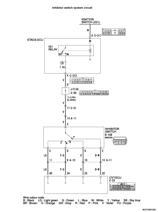
- B-109 Inhibitor switch connector
- C-33 CVT-ECU connector
|
|
|
Check the terminals for a contact status problem and internal short circuit.
|
|
|
Q.
Is the check result normal?
|
|
|
 Repair the defective connector. Repair the defective connector.
|
|
|
|
|
|
Between the C-313 ETACS-ECU connector (terminal No. 4) and the B-109 inhibitor switch connector (terminal No. 3)
|
|
|
Q.
Is the check result normal?
|
|
|
Repair the wiring harness.
|
|
|
|
|
|
- Between B-109 inhibitor switch connector (terminal No. 2) and C-33 CVT-ECU connector (terminal No. 32)
- Between B-109 inhibitor switch connector (terminal No. 5) and C-33 CVT-ECU connector (terminal No. 45)
- Between B-109 inhibitor switch connector (terminal No. 8) and C-33 CVT-ECU connector (terminal No. 34)
- Between B-109 inhibitor switch connector (terminal No. 9) and C-33 CVT-ECU connector (terminal No. 33)
|
|
|
Q.
Is the check result normal?
|
|
|
Repair the wiring harness.
|
|
|
|
|
|
Q.
Is the check result normal?
|
|
|
Adjust the inhibitor switch and control cable.
|
|
|
|
|
|
Q.
Is the check result normal?
|
|
|
Replace the inhibitor switch.
|
|
|
|
|
|
Q.
Is the check result normal?
|


 Intermittent malfunction
 .
.