|
|
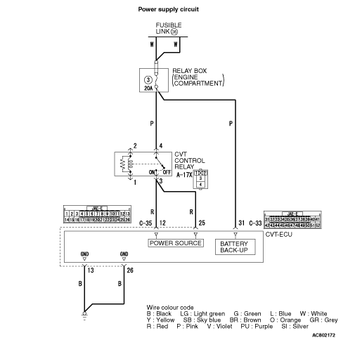
- A-17X CVT control relay connector
- C-35 CVT-ECU connector
|
|
|
Check each terminal for imperfect contact.
|
|
|
Q.
Is the check result normal?
|
|
|
 Repair the defective connector.
|
|
|
|
|
|
- Between A-17X CVT control relay connector (terminal No. 3) and C-35 CVT-ECU connector (terminal No. 12)
- Between A-17X CVT control relay connector (terminal No. 3) and C-35 CVT-ECU connector (terminal No. 25)
|
|
|
Q.
Is the check result normal?
|
|
|
Repair the wiring harness.
|
|
|
|
|
|
- Between C-35 CVT-ECU (terminal No. 13) and body earth
- Between C-35 CVT-ECU (terminal No. 26) and body earth
|
|
|
Q.
Is the check result normal?
|
|
|
Repair the wiring harness.
|
|
|
|
|
|
Recheck the trouble symptom.
|
|
|
Q.
Does the malfunction take place again?
|


 Go to Step 2.