|
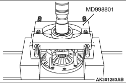
Use the special tool Bearing remover (MD998801) to remove the bearings.
|
|
|
1.Install the spacer on the back of each side gear, then install the side gears into
the differential case.
| note |
Use spacers of a medium thickness (0.93 - 1.00 mm) when installing new side gears.
|
|

|
2.Attach the washer to the back of each pinion, make both pinions engage with the side gears
simultaneously, and bring the pinions into position while turning the gear set.
|

|
3.Insert the pinion shaft.
|

|
4.Measure the backlash between the side gears and pinions.
Standard value: 0.025 - 0.150 mm
(For backlash between differential gear and pinion)
5.If the backlash is not within the standard value range, replace the spacers with appropriately
selected ones and measure the backlash again.
| note |
The amount of the backlash must be the same on both side gears.
|
|

|
Orient the lock pin as shown in the drawing.
| note |
After assembling the lock pin, confirm that the top of the lock pin is lower than the
flange of the differential case.
|
|

|
Use the special tools to install the new ball bearings.
- Installer cap (MD998812)
- Installer adapter (MD998819)
|

|
Apply ATF to the bolts, and tighten the bolts to the specified torque of 135 ± 5
N·m in the shown sequence.
|

