|
|
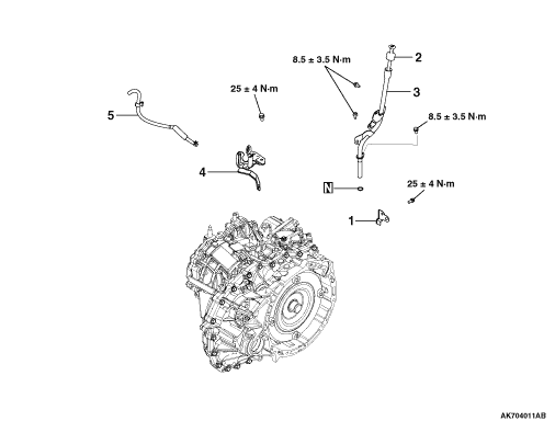
1.Remove the harness bracket from the transmission.
|
|
|
2.Remove the oil filler tube and oil level gage from the transmission.
|
|
|
3.Remove the control cable bracket and breather hose from the transmission.
|
|
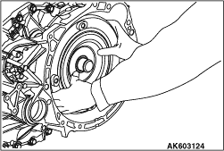
4.Remove the torque converter from the transmission.
|
|
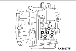
5.Remove the plug from the transmission case.
|
|
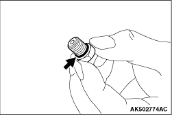
6.Remove the O-ring from the plug.
|
|
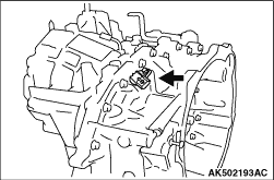
7.Remove the secondary pulley speed sensor from the converter housing, and detach the O-ring
from the sensor.
|

|
8.Remove the primary pulley speed sensor from the transmission case, and detach the O-ring
from the sensor.
|
|
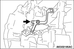
9.Remove the shift lever from the manual shaft.
|
|
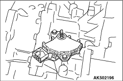
10.Remove the inhibitor switch from the transmission.
|
|
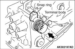
11.
| caution |
Be careful not to cause damage to the terminal body.
|
Remove the snap ring from the terminal body, and press the terminal body into the transmission
case.
|
|
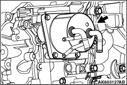
12.Remove the CVT fluid cooler from the transmission case, and detach the O-ring from the
cooler.
|
|
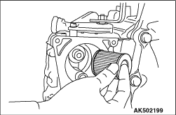
13.Remove the CVT fluid filter from the transmission case.
|

|
14.Remove the fastening bolts of converter housing.
Bolt symbol
|
A
|
B
|
Shank length mm
|
30
|
35
|
Quantity
|
18
|
5
|
|
|
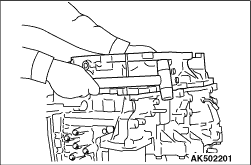
15.
| caution |
Be careful because adjusting shim of the drive sprocket may depart.
|
Remove the converter housing by tapping with a plastic hammer etc.
|

|
16.Using the special tools, remove the outer race of reduction gear bearing from the converter
housing.
- Rear axle shaft oil seal remover (MB990590)
- Slide hammer puller (MB992039)
17.Using cylinder gage etc., measure the mounting bore diameter of reduction gear bearing
outer race at the converter housing side; if the standard value is not satisfied, then replace
the converter housing.
Standard value: Φ61.949 - 61.979 mm
|

|
18.Using the special tools, remove the outer race of differential side bearing from the converter
housing.
- Rear axle shaft oil seal remover (MB990590)
- Slide hammer puller (MB992039)
19.Using cylinder gage etc., measure the mounting bore diameter of differential side
bearing outer race at the converter housing side; if the standard value is not satisfied, then
replace the converter housing.
Standard value: Φ67.949 - 67.979 mm
|
|
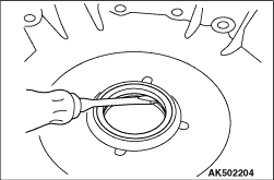
20.
| caution |
When removing the oil seal, be careful not to cause damage to the converter
housing.
|
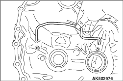
Using a flat blade screwdriver etc., remove the converter housing oil seal from the housing.
|
|
22.
| caution |
When removing the pipe, be careful not to bend it.
|
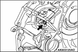
Remove the pipe from the converter housing.
|
|
23.Remove the plug from the converter housing.
|
|
24.Remove the O-ring from the plug.
|
|
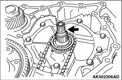
25.Remove the O-ring from the input shaft.
|

|
26.Remove the adjusting shim from the drive sprocket.
|

|
27.Remove the baffle plate.
|
|
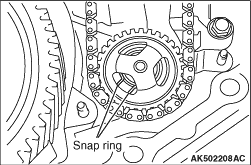
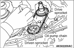
28.Expand the snap ring, and remove the driven sprocket, oil pump chain, and drive sprocket.
|

|
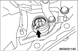
29.Remove the thrust washer from the oil pump cover.
|
|
30.Remove the snap ring from the oil pump.
|

|
31.Remove the reduction gear assembly from the transmission case.
|

|
32.Remove the differential assembly from the transmission case.
|

|
34.Remove the baffle plate.
|

|
35.Remove the baffle plate.
|

|
36.Remove the oil pump cover from the transmission case.
|
|
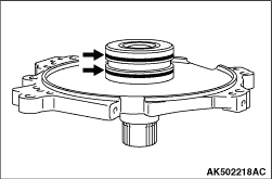
37.Remove the seal rings from the oil pump cover.
|
|
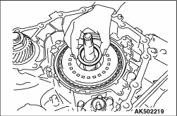
38.Remove the needle bearing from the forward clutch assembly.
|

|
39.Remove the oil pan from the transmission case.
40.Remove the magnet from the oil pan.
|

|
41.Remove the oil pan gasket from the transmission case.
|
|
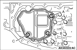
42.Remove the oil strainer.
Bolt symbol
|
A
|
B
|
C
|
Shank length mm
|
12
|
44
|
12
|
Quantity
|
1
|
1
|
1
|
|

|
43.Remove the O-ring from the oil strainer.
|
|
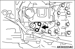
44.Remove the bracket from the control valve assembly.
|

|
45.Remove the manual lever.
|

|
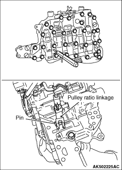
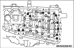
46.Remove the control valve assembly from the transmission case as follows:
(1)
Insert pins etc. (Φ3 mm) into linkage stopper holes of the control valve
assembly to fix the pulley ratio linkage.
(2)
Remove fastening bolts of the control valve assembly.
Bolt symbol
|
A
|
B
|
Shank length mm
|
54
|
44
|
Quantity
|
10
|
1
|
(3)
Remove the control valve assembly from the transmission case.
|
|
| note |
Tilt the control valve assembly, and after removing from the manual shaft side, remove
the terminal body from the transmission case.
|
|
|

|
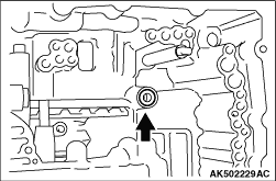
47.Remove the bush from the control valve.
|
|
48.Remove the lip seal from the transmission case.
|

|
49.Remove the valve body harness from the control valve.
|

|
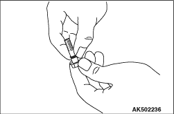
50.Remove the oil pump from the transmission case. (One fastening bolt is installed at the
backside from the transmission case side).
|
|
51.Remove the O-ring from the oil pump fastening bolt.
|

|
52.Remove the lip seal from the transmission case.
|

|
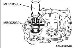
53.Using the special tools, remove outer race of the differential side bearing from the transmission
case.
- Rear axle shaft oil seal remover (MB990590)
- Slide hammer puller (MB992039)
54.Using cylinder gage etc., measure the mounting bore diameter of differential side
bearing outer race at the transmission case side; if the standard value is not satisfied, then
replace the CVT assembly.
Standard value: Φ67.949 - 67.979 mm
|

|
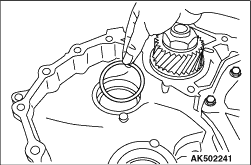
55.Remove the adjusting shim from the transmission case.
|
|
56.Using the special tools, remove outer race of the reduction gear bearing from the transmission
case.
- Rear axle shaft oil seal remover (MB990590)
- Slide hammer puller (MB992039)
57.Using cylinder gage etc., measure the mounting bore diameter of reduction gear bearing
outer race at the transmission case side; if the standard value is not satisfied, then replace
the CVT assembly.
Standard value: Φ61.949 - 61.979 mm
|
|
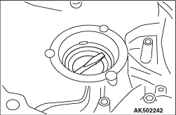
58.Remove the adjusting shim from the transmission case.
|
|
59.
| caution |
When removing the side oil seal, be careful not to cause damage to the
transmission case.
|
Using a flat blade screwdriver etc., remove the side oil seal from the transmission case.
|

|
60.Remove the detent spring from the transmission case.
|

|
61.Remove the forward clutch assembly from the transmission case.
|

|
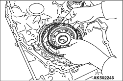
62.Remove the needle bearing on forward clutch drum side from the sun gear.
|
|
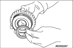
63.Remove the sun gear from the planet carrier.
|
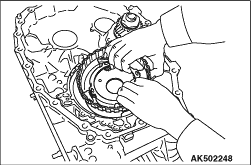
|
64.Remove the needle bearing on primary pulley side from the sun gear.
|
|
65.Remove the planet carrier from the transmission case.
|
|
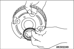
66.Remove the needle bearing from the planet carrier.
|

|
67.
| caution |
Check if there is damage, deformation, burn marks or permanent sets of
the dish plate, driven plate, snap ring, and drive plate. Replace any defective part.
|
Using a flat blade screwdriver etc., remove the reverse brake retaining plate, drive plate,
driven plate, and dish plate from the transmission case.
|

|
68.
| caution |
- Set the spring compressor right on top of the spring of spring
retainer assembly.
- Do not remove the return spring from the spring retainer assembly.
|
Using the special tool, Spring compressor (MB992139), compress the return spring, and
remove the snap ring from the transmission case.
69.Remove the retaining plate and return spring assembly.
|


|
70.
| caution |
Be careful. Do not use to much air pressure as this may cause the reverse
brake piston be stuck.
|
Feed the air in the oil hole shown in the diagram, and remove the reverse brake piston
from the transmission case.
|
|
1.
| caution |
- Do not re-use the reverse brake piston.
- Apply CVT fluid when installing the reverse brake piston.
|
Install the reverse brake piston, while turning it, on the transmission case.
|
|
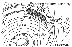
2.Align the spring portion of spring retainer assembly with the projections of the reverse
brake piston, and install the spring retainer assembly.
|

|
3.
| caution |
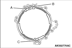
When installing the retaining plate, align the tangs at positions A, B,
C in the diagram.
|
Install the retaining plate on the transmission case.
|

|
4.
| caution |
- Set the spring compressor right on top of the spring of spring
retainer assembly.
- Do not re-use the snap ring.
- When installing the snap ring, make sure that the joint falls in the area A in the
diagram.
|
Using the special tool, Spring compressor (MB992139), compress the return spring, and
install the snap ring on the transmission case by means of a flat blade screwdriver etc.
|

|
5.Install the reverse brake retaining plate, drive plate, driven plate, and dish plate on
the transmission case.
|

|
6.
| caution |
- When conducting measurements, measure two or more places,
and find the average value.
- Do not re-use the snap ring.
- When installing the snap ring, make sure that the joint falls in the area A in the
diagram.
|
Using a flat blade screwdriver etc., install the snap-ring on the transmission case, and
measure clearance between the snap ring and retaining plate. Select the snap ring so as to obtain
standard value of the clearance. For selection of the snap ring, refer to "SERVICE SPECIFICATIONS".
Standard value: 1.2 - 1.5 mm
(For reverse brake clearance)
|

|
7.
| caution |
- Apply vaseline when installing the needle bearing.
- Be careful to attach the needle bearing in right direction.
|
Install the needle bearing on the reverse brake piston. Refer to A in the "IDENTIFICATION
OF NEEDLE BEARINGS" for right direction.
|
|
8.Install the planet carrier on the reverse brake.
|
|
9.
| caution |
- Apply vaseline when installing the needle bearing.
- Be careful to attach the needle bearing in right direction.
|
Install the needle bearing on the primary pulley side of the sun gear. Refer to B in the
"IDENTIFICATION OF NEEDLE BEARINGS" for right direction.
|
|
10.Install the sun gear on the planet carrier.
|
|
11.
| caution |
- Apply vaseline when installing the needle bearing.
- Be careful to attach the needle bearing in right direction.
|
Install the needle bearing on the forward clutch drum side of the sun gear. Refer to C
in the "IDENTIFICATION OF NEEDLE BEARINGS" for right direction.
|
|
12.Install the forward clutch assembly on the transmission case.
|


|
13.
| caution |
When conducting measurements, measure two or more places, and find the
average value.
|
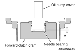
Measure the total end play A as follows:
(1)
Measure the distance M1 from the oil pump cover mounting surface of the transmission case
to the needle bearing mounting surface of the forward clutch drum.
(2)
Measure the distance M2 from the edge of oil pump cover to the mounting surface on the
transmission case.
(3)
Calculate the total end play by the following expression. Select the needle bearing
so that the total end play meets its standard value.
Total end play = M1 - M2 - bearing thickness
Standard value: 0.25 - 0.55 mm
(For total end play)
|
|
14.
| caution |
- Apply vaseline when installing the needle bearing.
- Be careful to attach the needle bearing in right direction.
|
Install the selected needle bearing on the forward clutch assembly. Refer to D in the
"IDENTIFICATION OF NEEDLE BEARINGS" for right direction.
|
|
15.
| caution |
- Do not re-use the seal rings.
- Apply vaseline when installing the seal rings.
|
Install the seal rings on the oil pump cover.
|
|
16.
| caution |
Do not re-use the bolt.
|
Install the detent spring on the transmission case, and tighten the fastening bolt at
the specified torque of 6.9 N·m.
|
|
17.
| caution |
- Do not re-use the O-ring.
- Apply CVT fluid when installing the O-ring.
|
Install the O-ring on the plug.
|
|
18.Install the plug on the converter housing to the specified torque of 7.5 N·m.
|
|
19.
| caution |
Do not bend the pipe when attaching it.
|
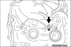
Install the pipe on the converter housing.
|
|
20.Install the clip, and tighten the bolt at the specified torque of 6.9 N·m.
|

|
21.
| caution |
- Do not re-use the outer race.
- Replace the outer race together with the inner race.
|
Using the special tools, install the differential bearing outer race.
- Real axle shaft bushing installer (MB990780)
- Bar (MB990779)
|


|
22.
| caution |
- When adjusting the preload, apply CVT fluid to the bearing
to make it roll smoothly.
- When conducting measurements, measure two or more places, and find the average value.
|
Measure the preload A of the differential assembly as follows:
(1)
Measure the distance M3 from the edge of transmission case to the mounting surface of
adjusting shim.
(2)
Install the differential assembly on the converter case, and measure the distance M4 from
the differential case to the edge of converter housing.
(3)
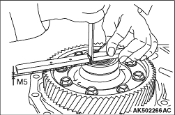
Install the outer race on differential side bearing, and measure the distance M5 from
the differential case to the outer race of differential side bearing.
(4)
Using the following expression, calculate the distance M6 from the edge of converter
housing to the outer race of differential side bearing.
M6 = M4 - M5
(5)
Using the following expression, calculate thickness of the adjusting shim.
Thickness of adjusting shim = M3 - M6 + preload
Standard value: 0.17 - 0.29 mm
(For differential preload)
|
|
23.
| caution |
Do not re-use the adjusting shim.
|
Install the selected shim on the transmission case. For selection of the adjusting shim,
refer to "SERVICE SPECIFICATIONS".
|

|
24.
| caution |
- Do not re-use the outer race.
- Replace the outer race together with the inner race.
|
Using the special tool, Real axle shaft bushing installer (MB990780), install the outer
race of differential side bearing on the transmission case.
|
|
25.
| caution |
- Do not re-use the outer race.
- Replace the outer race together with the inner race.
|
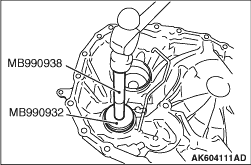
Using the special tools, install the outer race of reduction gear bearing on the converter
housing.
- Installer adapter (MB990932)
- Installer bar (MB990938)
|

|
26.
| caution |
- When adjusting the preload, apply CVT fluid to 1the bearing
to make it roll smoothly.
- When conducting measurements, measure two or more places, and find the average value.
|
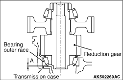
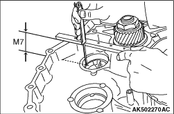
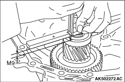
Measure the preload A of the reduction gear assembly in the following way.
(1)
Measure the distance M7 from the edge of transmission case to the mounting surface of
adjusting shim.
(2)
Install the reduction gear assembly on the converter housing, and measure the distance
M8 from the edge of reduction gear assembly to the edge of converter housing.
(3)
Install the outer race of reduction gear side bearing on the bearing, and measure the
distance M9 from the edge of reduction gear assembly to the outer race of reduction gear bearing.
(4)
Using the following expression, calculate the difference M10 from the outer race of
reduction gear bearing to the edge of converter housing.
M10 = M8 - M9
(5)
Using the following expression, calculate the thickness of adjusting shim.
Thickness of adjusting shim = M7 - M10 + preload
Standard value: 0.13 - 0.19 mm
(For reduction gear preload)
|
|
27.
| caution |
Do not re-use the adjusting shim.
|
Install the selected adjusting shim on the transmission case. For selection of the adjusting
shim, refer to "SERVICE SPECIFICATIONS".
|

|
28.
| caution |
- Do not re-use the outer race.
- Replace the outer race together with the inner race.
|
Using the special tools, install the outer race of reduction gear bearing on the transmission
case.
- Installer adapter (MB990932)
- Installer bar (MB990938)
|
|
29.
| caution |
- Do not re-use the lip seal.
- Apply CVT fluid when installing the lip seal.
|
Install the lip seal on the transmission case.
|
|
30.
| caution |
- Do not re-use the O-rings.
- Apply CVT fluid when installing the O-rings.
|
Install the O-rings on the oil pump fastening bolts.
|
|
31.Install the oil pump on the transmission case to the specified tightening torque of 19
N·m. (One fastening bolt is installed at the backside from the transmission case side.
Only this bolt should be tightened to the specified torque of 28 N·m).
|
|
32.
| caution |
Do not re-use the snap ring.
|
Install the snap ring on the oil pump.
|
|
33.
| caution |
- Do not re-use the lip seal.
- Apply CVT fluid or vaseline when installing the lip seal.
|
Install the lip seal on the transmission case.
|
|
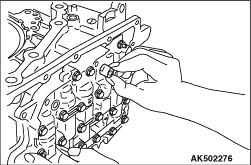
34.Install the valve body harness on the control valve.
|


|
35.Install the control valve assembly on the transmission case as follows:
(1)
Insert pins etc. (Φ3 mm) into linkage stopper holes of the control valve assembly
to fix the pulley ratio linkage.
(2)
Install the terminal body on the transmission case, while aligning the detent of terminal
body with the transmission case as shown in the diagram.
(3)
|
|
| caution |
Align the notch of pulley ratio linkage with the prong of pulley sensor.
|
|
Slide the control valve assembly from the bottom, and install it on the transmission case.
(4)
|
|
| caution |
Apply CVT fluid when attaching the bush.
|
|
Install the bush on the control valve assembly.
(5)
Install the fastening bolts of control valve assembly, and tighten to the specified torque
of 7.9 N·m.
Bolt symbol
|
A
|
B
|
Shank length mm
|
54
|
44
|
Quantity
|
10
|
1
|
|
|
36.Install the manual lever, and tighten the fastening nuts to the specified torque of 22.1
N·m.
|
|
37.Install the bracket on the control valve assembly, and tighten the fastening bolts to
the specified torque of 7.9 N·m.
|

|
38.
| caution |
- Do not re-use the O-ring.
- Apply CVT fluid when installing the O-ring.
|
Install the O-ring on the oil strainer.
|
|
39.Install the oil strainer, and tighten the fastening bolts to the specified torque of 7.9
N·m.
Bolt symbol
|
A
|
B
|
C
|
Shank length mm
|
12
|
44
|
12
|
Quantity
|
1
|
1
|
1
|
|
|
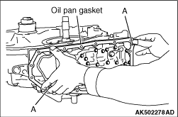
40.
| caution |
- Do not re-use the oil pan gasket.
- Remove any moisture, oil, and used gasket from the mounting surface of oil pan gasket.
- When installing the oil pan gasket, align the dowel pins of transmission case with
dowel pin holes A of the oil pan gasket.
|
Install the oil pan gasket on the transmission case.
41.Install the magnet on the oil pan.
|
|
42.
| caution |
When installing the oil pan, align the dowel pins of transmission case
with dowel pin holes A of the oil pan.
|
Install the oil pan on the transmission case, and tighten the bolts to the specified torque
of 7.9 N·m.
43.
| caution |
Do not re-use the drain plug gasket.
|
Install the drain plug and drain plug gasket on the transmission case, and tighten to
the specified torque of 34.3 N·m.
|
|
44.Install the oil pump cover on the transmission case, and fix the fastening bolts temporarily.
|
|
45.Install the baffle plate, and fix the fastening bolts temporarily.
|
|
46.Install the baffle plate, and tighten the fastening bolts to the specified torque of 5.9
N·m.
|

|
47.Install the bracket, and tighten the fastening bolts of the oil pump cover, baffle plate,
and bracket to the bolts to the specified torque of 26 N·m.
|
|
48.
| caution |
- Make sure the tang of thrust washer is aligned with the mounting
hole of oil pump cover.
- Apply vaseline when installing the thrust washer.
|
Install the thrust washer on the oil pump cover.
|
|
49.
| caution |
Pull the driven sprocket up softly to make sure it is securely attached.
|
Expand the snap ring, and install the driven sprocket, oil pump chain, and drive sprocket.
|


|
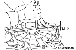
50.Measure the clearance A between the oil pump drive sprocket and the converter housing
as follows:
(1)
Measure the distance M11 between the edge of transmission case and the adjusting shim
mounting surface of drive sprocket.
(2)
Measure the distance M12 between the edge of converter housing and the surface contacting
the adjusting shim.
(3)
Use the following expression, to select the adjusting shim having the standard value.
Standard value of clearance = M11 + M12 - adjusting shim
thickness
Standard value: 0.10 - 0.23 mm
(For oil pump drive sprocket to converter housing clearance)
(4)
|
|
| caution |
Apply vaseline when installing the adjusting shim.
|
|
Install the selected adjusting shim on the drive sprocket. For selection of the adjusting
shim, refer to "SERVICE SPECIFICATIONS".
|
|
51.Install the baffle plate, and tighten the fastening nuts to the specified torque of 5.9
N·m.
|
|
52.
| caution |
- Do not re-use the O-ring.
- Apply CVT fluid when installing the O-ring.
|
Install the O-ring on the input shaft.
|
|
53.Install the differential assembly on the transmission case.
|
|
54.Install the reduction gear assembly on the transmission case.
|
|
55.
| caution |
- Do not re-use the O-ring.
- Apply CVT fluid when installing the O-ring.
|
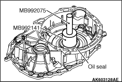
Using the special tool, install the converter housing oil seal on the converter housing.
- Oil seal installer (MB992141)
- Handle (MB992075)
Depth from the case edge:
Within - 1.0 ± 0.5 mm (recessed)
|

|
56.
| caution |
- Do not re-use the converter housing side oil seal.
- Apply CVT fluid when installing the converter housing side oil seal.
|
Using the special tools, install the converter housing side oil seal on the converter
housing.
- Oil seal installer (MB992206)
- Handle (MB992075)
|

|
57.
| caution |
- Remove any moisture, oil and oil sealant from the application
surface.
- Make sure the starting point and the ending point are about the middle between the
bolts.
|
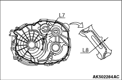
Apply the sealant on the converter housing mounting surface of the transmission case in
the following way
Specified sealant: Loctite 509
L1
|
9 mm
|
L2
|
5 mm
|
L3
|
Φ1.5 mm
|
L4
|
R8.5 mm
|
L5
|
R5 - 8 mm
|
L6
|
3 - 5 mm
|
L7
|
Φ17 mm
|
L8
|
3.5 mm
|
|
|
58.Install the converter housing on the transmission case, and tighten the fastening bolts
to the specified torque of 45 N·m.
Bolt symbol
|
A
|
B
|
Shank length mm
|
30
|
35
|
Quantity
|
18
|
5
|
|
|
59.
| caution |
Do not re-use the snap ring.
|
Install the snap ring on the terminal body.
|

|
60.
| caution |
- Do not re-use the side oil seal.
- Apply CVT fluid when installing the side oil seal.
|
Using the special tool, Oil seal installer (MB992140), install the side oil seal on the
transmission case.
Depth from the case edge:
Within - 1.8 ± 0.5 mm (recessed)
|
|
61.
| caution |
Do not re-use the inhibitor switch.
|
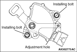
Install the inhibitor switch on the transmission case as follows:
(1)
Install the inhibitor switch on the transmission case.
(2)
Install the shift lever on the manual shaft, and tighten the fastening nuts to the specified
torque of 17.2 N·m.
(3)
Set the manual shaft at N position.
(4)
Insert pins etc. (Φ5 mm) in adjusting holes in both inhibitor switch and shift
lever, and after alignment, tighten the fastening bolts to the specified torque of 5.5 N·m.
|

|
62.
| caution |
- Do not re-use the O-ring.
- Apply CVT fluid when installing the O-ring.
|
Install the O-ring on the primary pulley speed sensor.
|
|
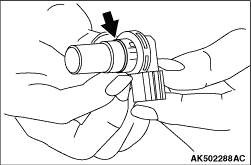
63.Install the primary pulley speed sensor on the transmission case, and tighten the fastening
bolts to the specified torque of 5.9 N·m.
|
|
64.
| caution |
- Do not re-use the O-ring.
- Apply CVT fluid when installing the O-ring.
|
Install the O-ring on the secondary pulley speed sensor.
|
|
65.Install the secondary pulley speed sensor on the transmission case, and tighten the fastening
bolts to the specified torque of 5.9 N·m.
|
|
66.
| caution |
- Apply CVT fluid or vaseline when installing the CVT fluid
filter.
- Do-not re-use the CVT fluid filter.
|
Install the CVT fluid filter on the transmission case.
|

|
67.
| caution |
- Do not re-use the O-ring.
- Apply CVT fluid when installing the O-ring.
- When installing O-ring, make sure that projection of the O-ring is put into the
groove on the filter.
|
Install the O-ring on the CVT fluid filter.
|
|
68.Install the CVT fluid cooler on the transmission case, and tighten the fastening bolts
to the specified torque of 4.2 N·m.
|
|
69.
| caution |
- Do not re-use the O-ring.
- Apply CVT fluid when installing the O-ring.
|
Install the O-ring on the plug.
|
|
70.Fasten the plug on the transmission case to the specified torque of 7.5 N·m.
|

|
71.
| caution |
When conducting measurements, measure two or more places, and find the
average value.
|
Install the converter on the transmission, and measure the size A to check if it meets
the standard value.
Standard size A: 15.9 mm
72.Install the control cable bracket and breather hose on the transmission case, and
tighten the fastening bolts to the specified torque of 25 ± 4 N·m.
73.Install the oil filler tube and oil level gage on the transmission case, and tighten
the fastening bolts to the specified torque of 8.5 ± 3.5 N·m.
74.Install the harness bracket on the transmission case, and tighten the fastening bolts
to the specified torque of 25 ± 4 N·m.
|