Pre-removal operation
- Transmission fluid draining (Refer to GROUP 22A, On-vehicle
Service, Transmission Oil Change
 .)<M/T> .)<M/T>
- CVT fluid draining (Refer to GROUP 23A, On-vehicle Service, CVT Fluid Change .)<CVT>
- A/T fluid draining (Refer to GROUP 23C, On-vehicle Service, A/T Fluid Change .)<A/T>
|
Post-installation operation
- Using your fingers, press the Ball Joint Dust Cover to check
for a crack or damage.
- Transmission fluid refilling (Refer to GROUP 22A, On-vehicle Service, Transmission
Oil Change .)<M/T>
- CVT fluid refilling (Refer to GROUP 23A, On-vehicle Service, CVT Fluid Change .) <CVT>
- A/T fluid refilling (Refer to GROUP 23C, On-vehicle Service, A/T Fluid Change .) <A/T>
- Check the beam direction of the headlamp (Low beam) (Refer to GROUP 54A - Headlamp
Aiming ).
|
|
Use special tool front hub and flange yoke holder (MB990767) to counter the hub as shown
in the figure to remove the driveshaft nut.
|
|
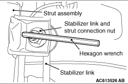
Use a hexagon wrench to remove the stabilizer link and strut connection nut as shown in
the figure.
|
|
1.
| caution |
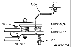
- Loosen the self-locking
nut (tie-rod end connection) from the ball joint, but do not remove here. Use the special tool.
- To prevent the special tool from dropping off, suspend it with a cord.
|
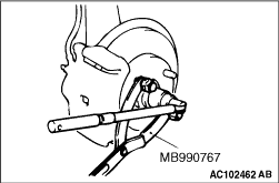
Install special tool ball joint remover (MB991897 or MB992011) as shown in the figure.
|
|
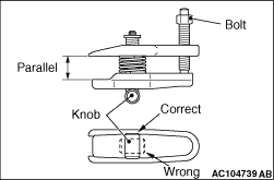
2.Turn the bolt and knob to make the special tool jaws parallel, then hand-tighten the bolt.
After tightening, check that the jaws are still parallel.
| note |
To adjust the special tool jaws to be parallel, set the orientation of the knob as shown
in the figure.
|
3.Unscrew the bolt to disconnect the ball joint.
|
|
1.
| caution |
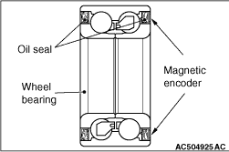
- The magnetic encoder collects metallic particles easily, because
it is magnetised. Make sure that the magnetic encoder does not collect metallic particles.
- When removing the driveshaft, make sure that it does not contact with the magnetic
encoder (integrated with the inner oil seal) to avoid damage.
|
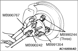
If the driveshaft is seized with the hub, use the following special tools to push the
driveshaft assembly out from the hub:
- Puller shaft (MB990242)
- Puller bar (MB990244)
- Front hub and flange yoke holder (MB990767)
- Puller body (MB991354)
|
|
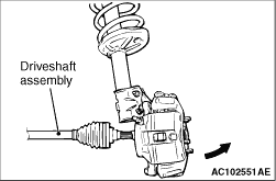
2.While pulling the lower side of the brake disc toward you, remove the driveshaft assembly
from the hub.
| caution |
- Never pull out the driveshaft
assembly from the EBJ assembly side. Otherwise, the TJ or ETJ assembly, EDJ or PTJ assembly
may be damaged. Always pull out from the TJ or ETJ side, EDJ or PTJ side with a lever.
- Care must be taken to ensure that the oil seal of the transmission is not damaged
by the spline part of the driveshaft assembly.
|
|
|
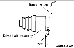
3.Insert a lever between the transmission case and driveshaft assembly, and then pull the
driveshaft assembly out from the transmission.
|

|
| caution |
Do not apply the vehicle weight to the wheel bearing with the driveshaft assembly removed.
If, however, the vehicle weight shall be applied to the bearing (in order to move the vehicle),
tighten the following special tools to the specified torque (144 - 176 N·m):
- Spacer (MB991000)
- Front hub remover and installer (MB991017)
|
|
|
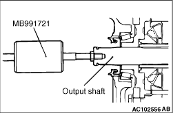
Use special tool slide hammer (MB991721) to remove the output shaft assembly.
|
|
| caution |
- The magnetic encoder collects metallic particles easily, because it is magnetised. Make
sure that the magnetic encoder should not collect metallic particles. Check that there is not
any trouble prior to reassembling it.
- When installing the driveshaft, make sure that it does not contact with the magnetic
encoder (integrated with the inner oil seal) to avoid damage.
- Care must be taken to ensure that the oil seal of the transmission is not damaged
by the spline part of the output shaft assembly or driveshaft assembly.
|
|
|
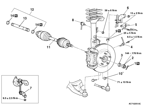
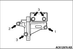
Tighten the mounting bolts in a sequence order as shown in the figure.
|
|
Use a hexagon wrench to install the stabilizer link and strut connection nut as shown
in the figure.
|
|
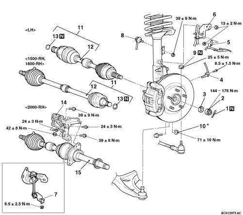
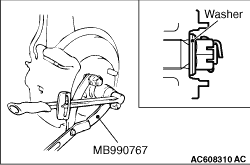
1.Incorporate the driveshaft assembly washer as shown in the illustration.
2.Using special tool front hub and flange yoke holder (MB990767), tighten the driveshaft
nut. At this time, tighten the nut to the specified lower limit torque so that the pin hole may
align with split pin.
Tightening torque: 144 - 176 N·m
3.If the pin hole does not align with the pin, tighten the driveshaft nut (less than
176 N·m) and find the nearest hole, then fit the split pin.
|