|
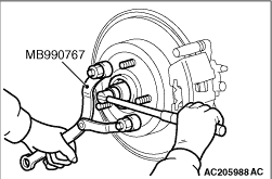
Use special tool front hub and flange yoke holder (MB990767) to counter the hub as shown in the figure to remove the driveshaft nut.
|
|
|
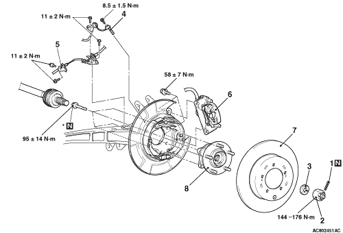
1.Remove the caliper assembly with brake hose.
|
|
|
2.Secure the removed caliper assembly with a wire or other similar material at a position where it will not interfere with the removal and installation of the rear wheel hub assembly.
|
|
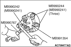
1.If the rear wheel hub assembly is seized with the rear driveshaft assembly, use the following special tools to push the rear driveshaft assembly out from the hub and then remove the rear wheel hub assembly.
- Puller shaft (MB990242)
- Puller bar (MB990244)
- Puller body (MB991354)
- Front hub and flange yoke holder (MB990767)
|
|
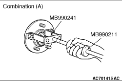
2.If the rear wheel hub assembly is seized with the knuckle, use the following special tools to remove the rear wheel hub assembly.
Combination (A)
- Slide hammer (MB990211)
- Rear axle shaft puller (MB990241)
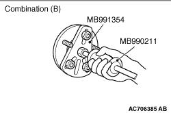
Combination (B)
- Slide hammer (MB990211)
- Puller body (MB991354)
|
|
| caution |
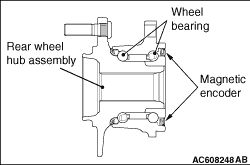
- The magnetic encoder collects metallic particles easily, because it is magnetised. Make sure that the magnetic encoder should not collect metallic particles. Check that there is not any trouble prior to reassembling it.
- When installing the drive shaft, make sure that it does not contact with the magnetic encoder (integrated with the inner oil seal) to avoid damage.
- Do not apply the vehicle weight on the rear wheel hub assembly before fully tightening the driveshaft nuts. Otherwise, the wheel bearing will be broken.
|
|
|
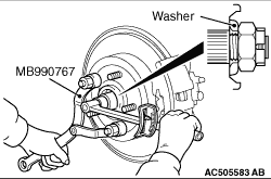
1.Incorporate the driveshaft washer as shown in the figure.
2.Using special tool front hub and flange yoke holder (MB990767), tighten the driveshaft nut. At this time, tighten the nut to the specified lower limit torque so that the pin hole may align with split pin.
Tightening torque: 144 - 176 N·m
3.If the pin hole does not align with the pin, tighten the driveshaft nut (less than 176 N·m) and find the nearest hole, then fit the split pin.
|