|
|
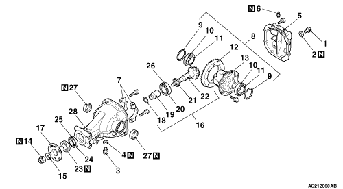
1.Remove the differential cover assembly.
|

|
2.Hold the following special tools in a vice, and install the differential carrier assembly to the special tool.
- Working base (MB990909)
- Working base adapter (MB991116)
|
|
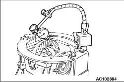
1.With the drive pinion locked in place, use a dial gauge to measure the drive gear backlash in four or more places on the drive gear.
Standard value: 0.11 - 0.16 mm
2.If the backlash is not within the standard value, adjust the final drive gear backlash (Refer to  ). ).
3.After the adjustment, inspect the final drive gear tooth contact.
|

|
1.Measure the drive gear runout at the shoulder on the reverse side of the drive gear.
Limit: 0.05 mm
2.When runout exceeds the limit value, check for foreign material between drive gear rear side and differential case, or for loose drive gear installation bolts.
3.When step (2) gives normal results, reposition the drive gear and differential case and remeasure.
4.If adjustment is impossible, replace the differential case assembly, or replace the drive gear and pinion as a set.
|
|
|
Check the tooth contact of drive gear by following the steps below.
|

|
1.Apply a thin, uniform coat of machine blue to both surfaces of the drive gear teeth.
|

|
2.
| caution |
If the drive gear is rotated too much, the tooth contact pattern will become unclear and difficult to check.
|
Insert special tool remover bar (MB990939) between the differential carrier and the differential case, and then rotate the companion flange by hand (once in the normal direction, and then once in the reverse direction) while applying a load to the drive gear so that the revolution torque (approximately 2.5 - 2.9 N·m) is applied to the drive pinion.
3.Check the tooth contact condition of the drive gear and drive pinion.
Standard tooth contact pattern
|
Problem
|
Solution
|
1. Narrow tooth side
2. Drive-side tooth surface
(the side applying power during forward
movement)
3. Wide tooth side
4. Coast-side tooth surface
(the side applying power during reverse
movement)

|
Tooth contact pattern resulting from excessive pinion height

The drive pinion is positioned too far from the centre of the drive gear.
|

Increase the thickness of the drive pinion rear shim, and position the drive pinion closer to the centre of the drive gear. Also, for backlash adjustment, position the drive gear farther from the drive pinion.
|
Tooth contact pattern resulting from insufficient pinion height.

The drive pinion is positioned too close to the centre of the drive gear.
|

Decrease the thickness of the drive pinion rear shim, and position the drive pinion farther from the centre of the drive gear. Also, for backlash adjustment,
position the drive gear
closer to the drive pinion.
|
| note |
Check the tooth contact pattern to confirm that the adjustments of the pinion height and backlash have been done properly. Continue to adjust the pinion height and backlash until the tooth contact pattern resembles the standard pattern. If, even after adjustments have been made, the correct tooth contact pattern cannot be obtained, it means that the drive gear and the drive pinion have become worn beyond the allowable limit. Replace the gear set.
|
|

|
Use the wooden handle of a hammer to remove the differential case assembly, differential side bearing spacers and differential side bearing outer races.
| note |
Keep the right and left side bearings and side bearing spacers separate, so that they do not become mixed during reassembly.
|
|

|
Use the following special tools to pull out the side bearing inner races.
- Side bearing puller (MB990810)
- Side bearing cap (MB990811)
| note |
There are two notches provided (at the differential case side) for the claw part of the special tools; use special tool MB990810 at that position.
|
|

|
1.Make the mating marks to the differential case and the drive gear.
2.Loosen the drive gear attaching bolts in a diagonal sequence to remove the drive gear.
|

|
Use special tool end yoke holder (MB990850) to hold the companion flange, and then remove the companion flange self-locking nut.
|
|
|
1.
| caution |
The mating mark made on the companion flange must not be on the coupling surface of the companion flange and the front propeller shaft.
|
Make mating marks on the drive pinion and companion flange.
|

|
2.Use special tool side bearing puller (MB990810) to pull out the companion flange.
|

|
Use special tool rear axleshaft bearing remover (MB990560) to pull out the drive pinion rear bearing inner race.
|

|
Use special tool remover bar (MB990939) to remove the drive pinion front bearing outer race.
|

|
Use special tool remover bar (MB990939) to remove the drive pinion rear bearing outer race.
|