|
|
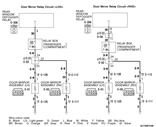
If either of the door mirror heater element does not work, the power supply or earth to
the heater element, or heater element itself may be defective.
|
|
|
- Door mirror heater elements failed
- Wiring harness or connector failure
|
|
|
Q.
Which of door mirror heater elements does not work?
|
|
|
Driver’s door mirror : Go to Step 10. : Go to Step 10.
|
|
|
|
|
|
Passenger’s door mirror : Go to Step 2.
|
|
|
|
|
|
Q.
Is the check result normal?
|
|
|
 Repair the defective connector. Repair the defective connector.
|
|
|
|
|
|
Check the heater element of the door mirror (RH). (Refer to Heater Element Check  .) .)
|
|
|
Q.
Is the check result normal?
|
|
|
Replace the mirror glass of the door mirror assembly (RH).
|
|
|
|
|
|
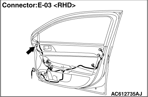
(1)Disconnect the connector, and measure at the wiring harness side.
|
|
|
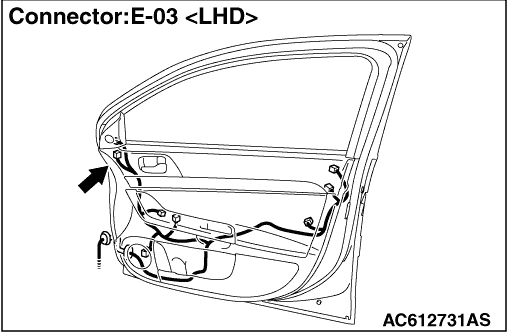
(2)Resistance between E-03 door mirror assembly (RH) connector terminal No. 5 and
body earth
OK: Continuity (2 Ω or less)
|
|
|
Q.
Is the check result normal?
|
|
|
- Check the earth wires for open circuit.
|
|
|
Q.
Is the check result normal?
|
|
|
 Intermittent malfunction (Refer to GROUP 00 - How to Use Troubleshooting/Inspection
Service Points - How to Cope with Intermittent Malfunction ). Intermittent malfunction (Refer to GROUP 00 - How to Use Troubleshooting/Inspection
Service Points - How to Cope with Intermittent Malfunction ).
|
|
|
|
|
|
Repair the wiring harness.
|
|
|
|
|
|
(1)Turn the ignition switch to the ON position.
|
|
|
(2)Turn on the rear window defogger switch.
|
|
|
(3)Disconnect the connector, and measure at the wiring harness side.
|
|
|
(4)Measure the voltage between E-03 door mirror assembly (RH) connector terminal No.
1 and body earth.
OK: Battery voltage
|
|
|
Q.
Is the check result normal?
|
|
|
Intermittent malfunction (Refer to GROUP 00 - How to Use Troubleshooting/Inspection
Service Points - How to Cope with Intermittent Malfunction ).
|
|
|
|
|
|
Q.
Is the check result normal?
|
|
|
Repair the damaged connector.
|
|
|
|
|
|
- Check the power supply line for open circuit.
|
|
|
Q.
Is the check result normal?
|
|
|
Repair the wiring harness.
|
|
|
|
|
|
Check that the heater element of the door mirror (RH) functions normally.
|
|
|
Q.
Is the check result normal?
|
|
|
Intermittent malfunction (Refer to GROUP 00 - How to Use Troubleshooting/Inspection
Service Points - How to Cope with Intermittent Malfunction ).
|
|
|
|
|
|
Replace the door mirror assembly (RH).
|
|
|
|
|
|
Check the heater element of the door mirror (LH). (Refer to Heater Element Check .)
|
|
|
Q.
Is the check result normal?
|
|
|
Replace the mirror glass of the door mirror assembly (LH).
|
|
|
|
|
|
Q.
Is the check result normal?
|
|
|
Repair the defective connector.
|
|
|
|
|
|
(1)Disconnect the connector, and measure at the wiring harness side.
|
|
|
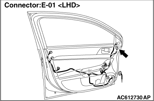
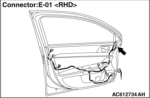
(2)Measure the resistance between E-01 door mirror assembly (LH) connector terminal
No. 5 and body earth.
OK: Continuity(2 Ω or less)
|
|
|
Q.
Is the check result normal?
|
|
|
- Check the earth wires for open circuit.
|
|
|
Q.
Is the check result normal?
|
|
|
Intermittent malfunction (Refer to GROUP 00 - How to Use Troubleshooting/Inspection
Service Points - How to Cope with Intermittent Malfunction ).
|
|
|
|
|
|
Repair the wiring harness.
|
|
|
|
|
|
(1)Turn the ignition switch to the ON position.
|
|
|
(2)Turn on the rear window defogger switch.
|
|
|
(3)Disconnect the connector, and measure at the wiring harness side.
|
|
|
(4)Voltage between E-01 door mirror assembly (LH) connector terminal No. 1 and body
earth.
OK: Battery voltage
|
|
|
Q.
Is the check result normal?
|
|
|
Intermittent malfunction (Refer to GROUP 00 - How to Use Troubleshooting/Inspection
Service Points - How to Cope with Intermittent Malfunction ).
|
|
|
|
|
|
Q.
Is the check result normal?
|
|
|
Repair the damaged connector.
|
|
|
|
|
|
- Check the power supply line for open circuit.
|
|
|
Q.
Is the check result normal?
|
|
|
Repair the wiring harness.
|
|
|
|
|
|
Check that the heater element works normally.
|
|
|
Q.
Is the check result normal?
|
|
|
Intermittent malfunction (Refer to GROUP 00 - How to Use Troubleshooting/Inspection
Service Points - How to Cope with Intermittent Malfunction ).
|
|
|
|
|
|
Replace the door mirror assembly (LH).
|
|
|
|