|
|
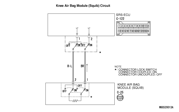
Only when the frontal impact exceeding the threshold is simultaneously detected (turned ON) by the front impact sensor as well as by the analogue G-sensor and safing G-sensor in SRS-ECU, the electric current is supplied from SRS-ECU to the knee air bag module (squib).
|
|
|
The code is set when the SRS-ECU driver’s knee air bag module (squib) circuit is shorted to earth.
|
|
|
- Damaged wiring harness and connectors
- Driver’s knee air bag module (squib) harness shorted to earth
- Malfunction of SRS-ECU
|
|
|
Use M.U.T.-III to diagnose the CAN bus lines.
|
|
|
Q.
Is the check result normal?
|
|
|
 Repair the CAN bus line (Refer to GROUP 54C - Troubleshooting Repair the CAN bus line (Refer to GROUP 54C - Troubleshooting  ). ).
|
|
|
|
|
|
(1)Connect the negative battery terminal.
|
|
|
(2)After erasing the diagnosis code memory, check the diagnosis code again.
|
|
|
(3)Disconnect the negative battery terminal.
|
|
|
Q.
Is the diagnosis code No. B1B10 set?
|
|
|
Intermittent malfunction (Refer to GROUP 00 - How to Use Troubleshooting/Inspection Service Points - How to Cope with Intermittent Malfunction ).
|
|
|
|
|
|
(1)Check that the negative battery terminal is disconnected. If the negative battery terminal is connected, disconnect it.
|
|
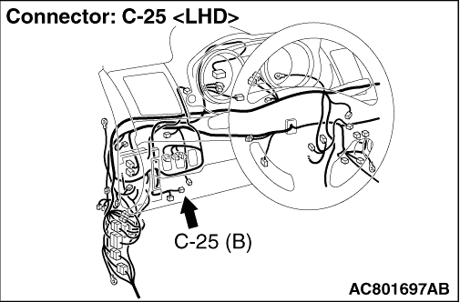
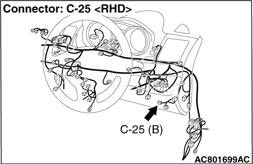
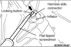
(2)Use the flat-tipped screwdriver to pull out the locking button of harness side connector. After releasing the lock, disconnect the C-25 harness side connector.
|
|
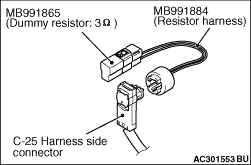
(3)Connect dummy resistor (MB991865) to special tool resistor harness (MB991884).
(4)Connect the special tool resistor harness to the C-25 harness side connector.
(5)Connect the negative battery terminal.
(6)After erasing the diagnosis code memory, check the diagnosis code again.
(7)Disconnect the negative battery terminal.
Q.
Is the diagnosis code No. B1B10 set?
 Go to Step 4. Go to Step 4.
Replace the driver’s knee air bag module (Refer to ). Then go to Step 5.
|
|
|
(1)Check that the negative battery terminal is disconnected. If the negative battery terminal is connected, disconnect it.
|

|
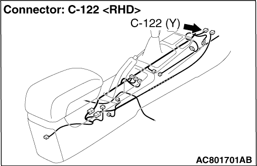
(2)While pushing the part "A" indicated in the figure of the harness side connector, turn the lock lever to the direction of the arrow to release the lock lever, and disconnect the C-122 SRS-ECU connector.
|
|
(3)
| danger |
To release the SRS-ECU connector short spring in the following operations, disconnect this harness side connector, and keep the squib circuit shorted.
|
Use the flat-tipped screwdriver to pull out the locking button of harness side connector. After releasing the lock, disconnect the C-25 harness side connector.
|
|
(4)
| caution |
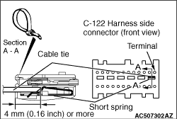
The short spring may not be released due to the insufficient insertion. Therefore, insert the insulator for 4 mm or more.
|
Insert an insulator (width: 3 mm, thickness: 0.5 mm) such as cable tie between the terminal 1/2 and the short spring, and release the short spring.
(5)Take the measurements below at the C-122 harness side connector.
- Continuity between terminal No. 1/2 and body earth
OK: No continuity
Q.
Is the check result normal?
Go to Step 5.
Repair the wiring harness between the C-122 SRS-ECU connector terminal No. 1/2 and the C-25 knee air bag module connector terminal No. 2/1.
|
|
|
Q.
Is the diagnosis code No. B1B10 set?
|
|
|
Replace SRS-ECU (Refer to ).
|
|
|
|
|
|
Intermittent malfunction (Refer to GROUP 00 - How to Use Troubleshooting/Inspection Service Points - How to Cope with Intermittent Malfunction ).
|
|
|
|