Inspection Procedure 1: The Diagnosis Code is not Set.
| caution | Before replacing the ECU, ensure that the power supply circuit, the earth circuit and the communication circuit are normal. |




COMMENTS ON TROUBLE SYMPTOM
PROBABLE CAUSES
- Malfunction of the headlamp automatic levelling-ECU
- Damaged harness wires and connectors
DIAGNOSIS PROCEDURE
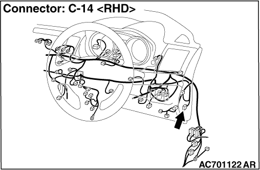
STEP 1. Connector check: C-14 headlamp automatic levelling-ECU connector
Q.
Is the check result normal?


STEP 2. Resistance measurement at the C-14 headlamp automatic levelling-ECU connector.
| (1)Disconnect the connector, and measure the resistance at the wiring harness-side connector. |
| (2)Measure the resistance between the C-14 headlamp automatic levelling-ECU connector terminal No. 14 and the body earth. OK: Continuity exists (2 Ω or less) |
Q.
Is the check result normal?

STEP 3. Wiring harness check between the C-14 headlamp automatic levelling-ECU connector terminal No. 14 and the body earth
- Check the earth wires for open circuit.
Q.
Is the check result normal?
- Go to Step 4.
STEP 4. Voltage measurement at the C-14 headlamp automatic levelling-ECU connector.
| (1)Disconnect the connector, and measure at the wiring harness-side connector. |
| (2)Turn the ignition switch to the ON position. |
| (3)Voltage between the C-14 headlamp automatic levelling-ECU connector terminal No. 1 and the body earth OK: System voltage |
Q.
Is the check result normal?
STEP 5. Wiring harness check between the C-14 headlamp automatic levelling-ECU connector terminal No. 1 and the fusible link (34) <1500, 1800, 2000-PETROL> or (44) <2000-DIESEL>
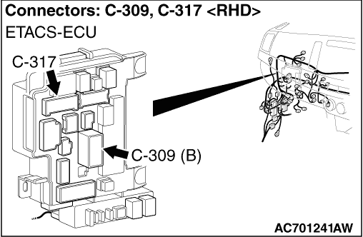
| note | Before the wiring harness check, check the ETACS-ECU connectors C-309 and C-317, and the intermittent connector C-128. Then, repair them if necessary. |
- Check the power supply line for open circuit.
Q.
Is the check result normal?
STEP 6. Connector check: C-26 diagnosis connector
Q.
Is the check result normal?
STEP 7. Wiring harness check between the C-14 headlamp automatic levelling-ECU connector terminal No. 5/7 and the C-26 diagnosis connector terminal No. 1/10
| note | Before the wiring harness check, check the intermittent connectors C-127 and C-128, and then repair that if necessary. |
- Check the communication lines for open circuit and short circuit.
Q.
Is the check result normal?
STEP 8. Retest the system
Q.
Is the diagnosis code set?

