Code No.B16A1 Tail Lamp (LH) Circuit Open <Open circuit in the position lamp (LH) circuit, tail lamp (LH) circuit, and the licence plate lamp circuit>
Code No.B16A8 Tail Lamp (LH) Circuit Short <Short circuit in the position lamp (LH) circuit, tail lamp (LH) circuit or the licence plate lamp circuit>
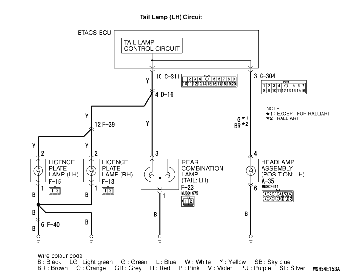


DIAGNOSTIC FUNCTION
JUDGEMENT CRITERIA
PROBABLE CAUSES
- Malfunction of bulbs
- Damaged harness wires and connectors
- Malfunction of the ETACS-ECU
DIAGNOSIS PROCEDURE
STEP 1. Bulb check
Q.
Is the check result normal?


STEP 2. Connector check: A-35 headlamp assembly (LH) connector, F-23 rear combination lamp (LH) connector, F-15 licence plate lamp (LH) connector and F-13 licence plate lamp (RH) connector
Q.
Is the check result normal?
STEP 3. Resistance measurement at the A-35 headlamp assembly (LH) connector, F-23 rear combination lamp (LH) connector, F-15 licence plate lamp (LH) connector and F-13 licence plate lamp (RH) connector
| (1)Disconnect the connector, and measure at the wiring harness side. |
(2)Measure the resistance between the connector terminal of lamp which does not illuminate and the body earth.
|
Q.
Is the check result normal?

STEP 4. Wiring harness check between the A-35 headlamp assembly (LH) connector terminal No. 6, F-23 rear combination lamp (LH) connector terminal No. 1, F-15 licence plate lamp (LH) connector terminal No. 1 or F-13 licence plate lamp (RH) connector terminal No. 1 and the body earth
| note | Prior to the wiring harness inspection, check intermediate connector F-40, and repair if necessary. |
- Check the earth wires for open circuit.
Q.
Is the check result normal?
STEP 5. Connector check: C-304 and C-311 ETACS-ECU connector
Q.
Is the check result normal?
STEP 6. Wiring harness check between the A-35 headlamp assembly (LH) connector terminal No. 4, F-23 rear combination lamp (LH) connector terminal No. 3, F-15 licence plate lamp (LH) connector terminal No. 2 or F-13 licence plate lamp (RH) connector terminal No. 2 and C-304 ETACS-ECU connector terminal No. 3 or C-311 ETACS-ECU connector terminal No. 10
| note | Prior to the wiring harness inspection, check intermediate connectors D-16 and F-39, and repair if necessary. |
- Check the power supply lines for open circuit and short circuit.
Q.
Is the check result normal?
STEP 7. Check whether the diagnosis code is reset.
| (1)Erase the diagnosis code. |
| (2)Turn the ignition switch from "LOCK" (OFF) position to "ON" position. |
| (3)Check if diagnosis code is set. |
Q.
Is the diagnosis code set?
