|
|
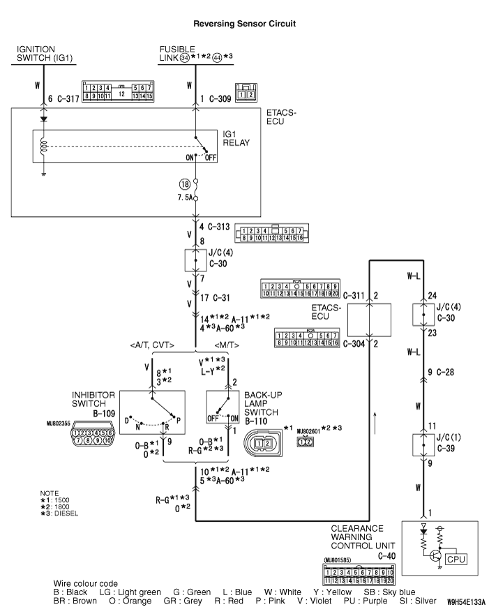
If obstacle is not detected even when the selector or shift lever is shifted to "R" (reverse)
position, the wiring harness, connectors, inhibitor switch <A/T, CVT>,
back-up lamp switch <M/T>, or clearance warning control unit may
be defective. In addition, obstacle is not detected when the ultrasonic noise is received.
|
|
|
- Damaged harness wires and connectors
- Malfunction of the inhibitor switch <A/T, CVT> or back-up
lamp switch <M/T>
- Malfunction of clearance warning control unit
|
|
|
Q.
Are there anything that interferes with the communication (things that generate radio
waves such as magnets and an air-cleaning device that has a power plug) near the reversing sensor
(forward distance warning sensor and corner clearance sensor)?
|
|
|
 Move away or remove things that interfere with the communication (things that
generate radio waves such as magnets and a air-cleaning device that has a power plug) near the
sensor (forward distance warning sensor and corner clearance sensor). Move away or remove things that interfere with the communication (things that
generate radio waves such as magnets and a air-cleaning device that has a power plug) near the
sensor (forward distance warning sensor and corner clearance sensor).
|
|
|
|
|
|
Q.
Is the check result normal?
|
|
|
 Repair the defective connector. Repair the defective connector.
|
|
|
|
|
|
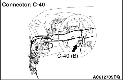
(1)Disconnect C-40 clearance warning control unit connector, and measure at the wiring
harness side.
|
|
|
(2)Turn the ignition switch to the "ON" position, and move the selector lever <A/T,
CVT> or the shift lever <M/T> to the "R" position.
|
|
|
(3)Measure the voltage between terminal No. 1 and earth.
OK: System voltage
|
|
|
Q.
Is the check result normal?
|
|
|
- Check the communication line for open circuit or short circuit.
|
|
|
Q.
Is the check result normal?
|
|
|
Repair the wiring harness.
|
|
|
|
|
|
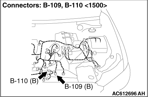
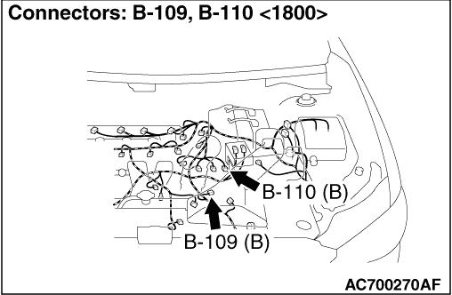
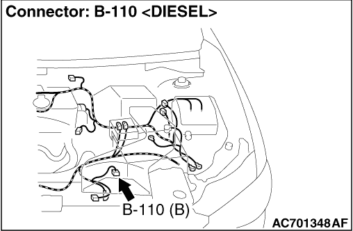
(1)Disconnect B-109 inhibitor switch connector <A/T, CVT> or
B-110 back-up lamp switch connector <M/T>, and measure at the wiring
harness side.
|
|
|
(2)Turn the ignition switch to "ON" position.
|
|
|
(3)Measure the voltage between or B-109 inhibitor switch connector <A/T,
CVT> terminal No. 8 <1500> or 3 <1800> or B-110
back-up lamp switch <M/T> connector terminal No. 2 and earth.
OK: System voltage
|
|
|
Q.
Is the check result normal?
|
|
|
- Check the communication line for open circuit or short circuit.
|
|
|
Q.
Is the check result normal?
|
|
|
The trouble can be an intermittent malfunction (Refer to GROUP 00 - How
to use Troubleshooting/inspection Service Points - How to Cope with Intermittent
Malfunction  ). ).
|
|
|
|
|
|
Repair the wiring harness.
|
|
|
|
|
|
Check the continuity of the inhibitor switch <A/T, CVT> or
the back-up lamp switch <M/T>.(GROUP 23A - On-vehicle Service,
Inhibitor Switch Continuity Check <CVT>,
GROUP 23C - On-vehicle Service, Inhibitor Switch Continuity Check <A/T> or
GROUP 22C - Transmission, Transmission Inspection )
|
|
|
Q.
Is the check result normal?
|
|
|
The trouble can be an intermittent malfunction (Refer to GROUP 00 - How
to use Troubleshooting/inspection Service Points - How to Cope with Intermittent
Malfunction ).
|
|
|
|
|
|
Replace the inhibitor switch <A/T, CVT> or back-up
lamp switch <M/T>.
|
|
|
|
|
|
Check if an obstacle is detected when the selector or shift lever is shifted to the "R"
(Reverse) position.
|
|
|
Q.
Is the check result normal?
|
|
|
The trouble can be an intermittent malfunction (Refer to GROUP 00 - How
to use Troubleshooting/inspection Service Points - How to Cope with Intermittent
Malfunction ).
|
|
|
|
|
|
Replace the clearance warning control unit.
|
|
|
|