Inspection Procedure 7: Check the hands free-ECU power supply circuit.
| caution | Before replacing the ECU, ensure that the power supply circuit, the earth circuit and the communication circuit are normal. |



CIRCUIT OPERATION
- The power supply to the hands free-ECU is provided by the fusible link (34).
- If the power supply system from the battery is defective, the system operates by the power supply from the ignition switch (IG1).
TECHNICAL DESCRIPTION (COMMENT)
PROBABLE CAUSES
- Damaged harness wires and connectors
- Malfunction of the hands free-ECU
DIAGNOSIS PROCEDURE |
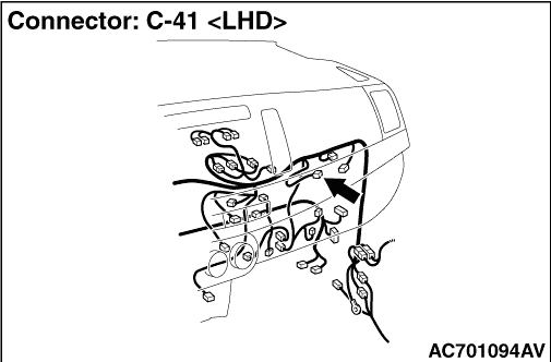
STEP 1. Connector check: C-41 hands free-ECU connector |
Q.
Is the check result normal?
|
 Go to Step 2. Go to Step 2. |
|
 Repair the defective connector. Repair the defective connector. |
|
STEP 2. Resistance measurement at C-41 hands free-ECU connector. |
| (1)Disconnect the connector, and measure at the wiring harness side. |
| (2)Check the continuity between terminal 15 and earth. OK: Continuity exists (2 Ω or less) |
Q.
Is the check result normal?
|
| Go to Step 4. |
|
| Go to Step 3. |
|
STEP 3. Check the wiring harness between C-41 hands free-ECU connector terminal No.15 and body earth. |
Q.
Is the check result normal?
|
| Replace the hands free-ECU. The system should communicate with the hands free-ECU normally. |
|
| Repair the wiring harness. |
|
STEP 4. Check the wiring harness between C-41 hands free-ECU connector terminal No.13 and fusible link (36) <PETROL> or (38) <DIESEL>. |
|
Q.
Is the check result normal?
|
| Replace the hands free-ECU. The system should communicate with the hands free-ECU normally. |
|
| Repair the wiring harness. |
|