Diagnosis Item 13: Diagnose when the M.U.T.-III cannot receive the data sent by transmission assembly (TC-SST-ECU) <RALLIART>
| caution | When servicing a CAN bus line, earth
yourself by touching a metal object such as an unpainted water pipe. If you fail to do, a component
connected to the CAN bus line may be broken. |
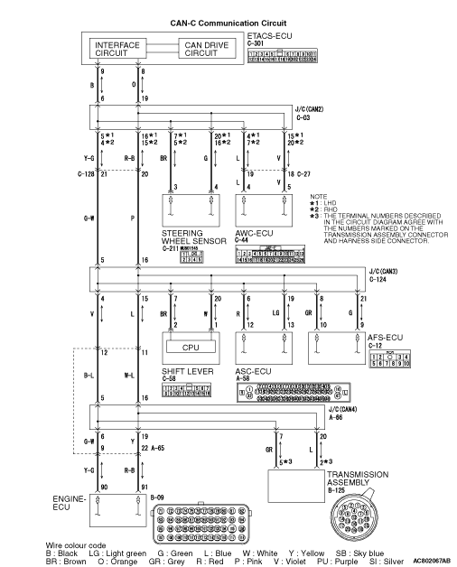


FUNCTION
TROUBLE JUDGEMENT CONDITIONS
TROUBLESHOOTING HINTS
- Malfunction of the connector [joint connector (CAN4) or transmission
assembly (TC-SST-ECU) connector improperly connected]
- Malfunction of the wiring harness [open circuit between the transmission
assembly (TC-SST-ECU) and the joint connector (CAN4), power supply circuit to the transmission assembly]
- Faulty transmission assembly (TC-SST-ECU)
DIAGNOSIS PROCEDURE |
STEP 1. Connector check: A-66 joint connector (CAN4) and B-125 transmission assembly (TC-SST-ECU) connector |
|
Q.
Is the check result normal?
|
 Go to Step 2. Go to Step 2. |
|
 Repair the defective connector. Repair the defective connector. |
|
STEP 2. Check the wiring harness between B-125 transmission assembly (TC-SST-ECU) connector and A-66 joint connector (CAN4) |
|
| Disconnect transmission assembly (TC-SST-ECU) connector and joint connector (CAN4), and
check the following wiring harness for open circuit. |
| (1)The wiring harness between B-125 transmission assembly (TC-SST-ECU) connector terminal No.5
and A-66 joint connector (CAN4) terminal No.7 <CAN_H> OK: Continuity exists (2 Ω or less) |
| (2)The wiring harness between B-125 transmission assembly (TC-SST-ECU) connector terminal No.2
and A-66 joint connector (CAN4) terminal No.20 <CAN_L> OK: Continuity exists (2 Ω or less) |
Q.
Is the check result normal?
|
Check the power supply circuit of the transmission assembly (TC-SST-ECU). Refer
to GROUP 22E - Troubleshooting  <TC-SST>. <TC-SST>. |
|
| Repair the wiring harness. |
|