Diagnosis Item
28: Short to power supply or earth, open circuit or line-to-line short in the CAN-B bus lines
| caution |
When servicing a CAN bus line, earth
yourself by touching a metal object such as an unpainted water pipe. If you fail to do, a component
connected to the CAN bus line may be broken.
|
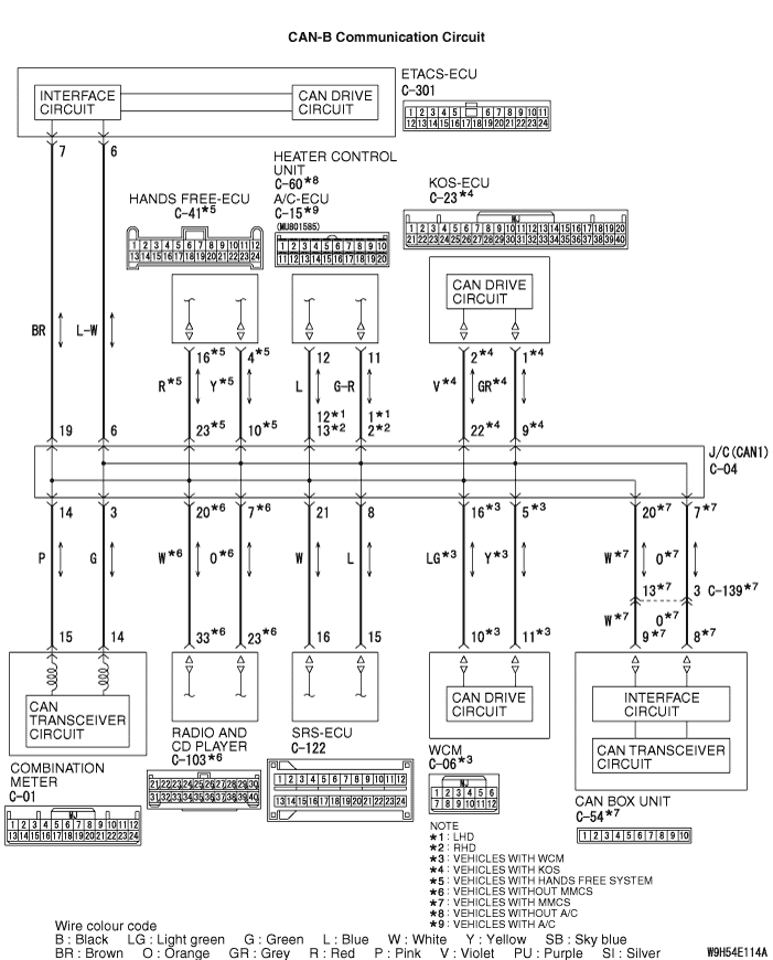

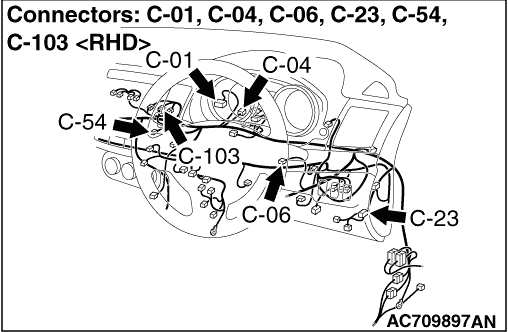


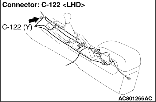


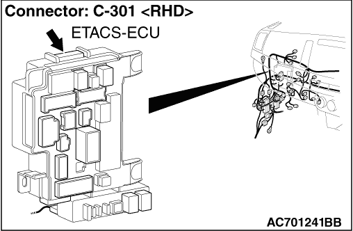
FUNCTION
TROUBLE JUDGEMENT CONDITIONS
TROUBLESHOOTING HINTS
- Malfunction of the connector (short to power supply or earth in connector
or improperly connected)
- Malfunction of the wiring harness (short to power supply or earth, open circuit
or line-to-line short in CAN bus lines)
- Faulty ECU(s) (internal short to power supply or earth)
|
|
STEP 1. Checking short to earth (resistance measurement)
|
|
|
| note |
This check determines whether there is a short to earth in the CAN-B bus line. If a short
to earth is present in either the CAN_H or CAN_L line, check the appropriate
line only.
|
|
|
|
| caution |
- Disconnect the negative battery terminal. For
details refer to
 . .
- A digital multimeter should be used. For details refer to .
- The test wiring harness should be used. For details refer to .
|
|
|
|
(1)Disconnect C-301 ETACS-ECU connector, and measure at the wiring harness side.
|
|
|
(2)Measure the resistance between C-301 ETACS-ECU connector terminal No.6 and body
earth. <CAN_H>
OK: 1 kΩ or more
|
|
|
(3)Measure the resistance between C-301 ETACS-ECU connector terminal No.7 and body
earth. <CAN_L>
OK: 1 kΩ or more
|
|
|
Q.
Is the check result normal?
|
|
|
 Go to Step 11. Go to Step 11.
|
|
|
|
|
|
 Go to Step 2. Go to Step 2.
|
|
|
|
|
|
STEP 2. Check the wiring harness between C-122 SRS-ECU connector and
C-04 joint connector (CAN1) for short to earth (resistance measurement).
|
|
|
| caution |
- Disconnect the negative battery terminal. For
details refer to .
- A digital multimeter should be used. For details refer to .
- The test wiring harness should be used. For details refer to .
|
|
|
|
(1)Disconnect joint connector (CAN1), and measure at the wiring harness side.
|
|
|
(2)Measure the resistance between C-04 joint connector (CAN1) terminal No.8 and body
earth.
OK: 1 kΩ or more
|
|
|
(3)Measure the resistance between C-04 joint connector (CAN1) terminal No.21 and body
earth.
OK: 1 kΩ or more
|
|
|
Q.
Is the check result normal?
|
|
|
Go to Step 3.
|
|
|
|
|
|
Go to Step 40.
|
|
|
|
|
|
STEP 3. Check the wiring harness between C-15 A/C-ECU connector <vehicles
with A/C> or C-60 heater control unit connector <vehicles without A/C> and C-04 joint connector
(CAN1) for short to earth (resistance measurement).
|
|
|
| caution |
- Disconnect the negative battery terminal. For
details refer to .
- A digital multimeter should be used. For details refer to .
- The test wiring harness should be used. For details refer to .
|
|
|
|
(1)Disconnect joint connector (CAN1), and measure at the wiring harness side.
|
|
|
(2)Measure the resistance between C-04 joint connector (CAN1) terminal No.1 <LHD> or
2 <RHD> and body earth. <CAN_H>
OK: 1 kΩ or more
|
|
|
(3)Measure the resistance between C-04 joint connector (CAN1) terminal No.12 <LHD> or
13 <RHD> and body earth. <CAN_L>
OK: 1 kΩ or more
|
|
|
Q.
Is the check result normal?
|
|
|
YES <vehicles with WCM> : Go to Step 4. : Go to Step 4.
|
|
|
|
|
|
YES <vehicles with KOS> : Go to Step 5.
|
|
|
|
|
|
NO : Go to Step 41.
|
|
|
|
|
|
STEP 4. Check the wiring harness between C-06 WCM connector and C-04
joint connector (CAN1) for short to earth (resistance measurement).
|
|
|
| caution |
- Disconnect the negative battery terminal. For
details refer to .
- A digital multimeter should be used. For details refer to .
- The test wiring harness should be used. For details refer to .
|
|
|
|
(1)Disconnect joint connector (CAN1), and measure at the wiring harness side.
|
|
|
(2)Measure the resistance between C-04 joint connector (CAN1) terminal No.5 and body
earth. <CAN_H>
OK: 1 kΩ or more
|
|
|
(3)Measure the resistance between C-04 joint connector (CAN1) terminal No.16 and body
earth. <CAN_L>
OK: 1 kΩ or more
|
|
|
Q.
Is the check result normal?
|
|
|
YES <vehicles without MMCS> : Go to Step 7.
|
|
|
|
|
|
YES <vehicles with MMCS> : Go to Step 6.
|
|
|
|
|
|
NO : Go to Step 42.
|
|
|
|
|
|
STEP 5. Check the wiring harness between C-23 KOS-ECU connector and
C-04 joint connector (CAN1) for short to earth (resistance measurement).
|
|
|
| caution |
- Disconnect the negative battery terminal. For
details refer to .
- A digital multimeter should be used. For details refer to .
- The test wiring harness should be used. For details refer to .
|
|
|
|
(1)Disconnect joint connector (CAN1), and measure at the wiring harness side.
|
|
|
(2)Measure the resistance between C-04 joint connector (CAN1) terminal No.9 and body
earth. <CAN_H>
OK: 1 kΩ or more
|
|
|
(3)Measure the resistance between C-04 joint connector (CAN1) terminal No.22 and body
earth. <CAN_L>
OK: 1 kΩ or more
|
|
|
Q.
Is the check result normal?
|
|
|
YES <vehicles without MMCS> : Go to Step 7.
|
|
|
|
|
|
YES <vehicles with MMCS> : Go to Step 6.
|
|
|
|
|
|
NO : Go to Step 43.
|
|
|
|
|
|
STEP 6. Check the wiring harness between C-54 CAN box unit connector
and C-04 joint connector (CAN1) for short to earth (resistance measurement).
|
|
|
| caution |
- Disconnect the negative battery terminal. For
details refer to .
- A digital multimeter should be used. For details refer to .
- The test wiring harness should be used. For details refer to .
|
|
|
|
(1)Disconnect joint connector (CAN1), and measure at the wiring harness side.
|
|
|
(2)Measure the resistance between C-04 joint connector (CAN1) terminal No.7 and body
earth. <CAN_H>
OK: 1 kΩ or more
|
|
|
(3)Measure the resistance between C-04 joint connector (CAN1) terminal No.20 and body
earth. <CAN_L>
OK: 1 kΩ or more
|
|
|
Q.
Is the check result normal?
|
|
|
YES <vehicles without hands free cellular phone system> : Go to Step 9.
|
|
|
|
|
|
YES <vehicles with hands free cellular phone system> : Go to Step 8.
|
|
|
|
|
|
NO : Go to Step 44.
|
|
|
|
|
|
STEP 7. Check the wiring harness between C-103 radio and CD player
connector and C-04 joint connector (CAN1) for short to earth (resistance measurement).
|
|
|
| caution |
- Disconnect the negative battery terminal. For
details refer to .
- A digital multimeter should be used. For details refer to .
- The test wiring harness should be used. For details refer to .
|
|
|
|
(1)Disconnect joint connector (CAN1), and measure at the wiring harness side.
|
|
|
(2)Measure the resistance between C-04 joint connector (CAN1) terminal No.7 and body
earth. <CAN_H>
OK: 1 kΩ or more
|
|
|
(3)Measure the resistance between C-04 joint connector (CAN1) terminal No.20 and body
earth. <CAN_L>
OK: 1 kΩ or more
|
|
|
Q.
Is the check result normal?
|
|
|
YES <vehicles without hands free cellular phone system> : Go to Step 9.
|
|
|
|
|
|
YES <vehicles with hands free cellular phone system> : Go to Step 8.
|
|
|
|
|
|
Go to Step 45.
|
|
|
|
|
|
STEP 8. Check the wiring harness between C-41 hands free-ECU connector
and C-04 joint connector (CAN1) for short to earth (resistance measurement).
|
|
|
| caution |
- Disconnect the negative battery terminal. For
details refer to .
- A digital multimeter should be used. For details refer to .
- The test wiring harness should be used. For details refer to .
|
|
|
|
(1)Disconnect joint connector (CAN1), and measure at the wiring harness side.
|
|
|
(2)Measure the resistance between C-04 joint connector (CAN1) terminal No.10 and body
earth. <CAN_H>
OK: 1 kΩ or more
|
|
|
(3)Measure the resistance between C-04 joint connector (CAN1) terminal No.23 and body
earth. <CAN_L>
OK: 1 kΩ or more
|
|
|
Q.
Is the check result normal?
|
|
|
Go to Step 9.
|
|
|
|
|
|
Go to Step 46.
|
|
|
|
|
|
STEP 9. Check the wiring harness between C-01 combination meter connector
and C-04 joint connector (CAN1) for short to earth (resistance measurement).
|
|
|
| caution |
- Disconnect the negative battery terminal. For
details refer to .
- A digital multimeter should be used. For details refer to .
- The test wiring harness should be used. For details refer to .
|
|
|
|
(1)Disconnect joint connector (CAN1), and measure at the wiring harness side.
|
|
|
(2)Measure the resistance between C-04 joint connector (CAN1) terminal No.3 and body
earth. <CAN_H>
OK: 1 kΩ or more
|
|
|
(3)Measure the resistance between C-04 joint connector (CAN1) terminal No.14 and body
earth. <CAN_L>
OK: 1 kΩ or more
|
|
|
Q.
Is the check result normal?
|
|
|
Go to Step 10.
|
|
|
|
|
|
Go to Step 47.
|
|
|
|
|
|
STEP 10. Check the wiring harness between C-301 ETACS-ECU connector
and C-04 joint connector (CAN1) for short to earth (resistance measurement).
|
|
|
| caution |
- Disconnect the negative battery terminal. For
details refer to .
- A digital multimeter should be used. For details refer to .
- The test wiring harness should be used. For details refer to .
- Strictly observe the specified wiring harness repair procedure. For details refer
to .
|
|
|
|
(1)Disconnect ETACS-ECU connector and joint connector (CAN1), and measure at the wiring
harness side.
|
|
|
(2)Measure the resistance between C-04 joint connector (CAN1) terminal No.6 and body
earth. <CAN_H>
OK: 1 kΩ or more
|
|
|
(3)Measure the resistance between C-04 joint connector (CAN1) terminal No.19 and body
earth. <CAN_L>
OK: 1 kΩ or more
|
|
|
Q.
Is the check result normal?
|
|
|
Go to Step 48.
|
|
|
|
|
|
Repair the wiring harness between C-301 ETACS-ECU connector and C-04 joint connector
(CAN1).
|
|
|
|
|
|
STEP 11. Checking short to power supply (voltage measurement)
|
|
|
| note |
This check determines whether there is a short to power supply in the CAN-B bus line.
If a failure is present in either the CAN_H or CAN_L line, check the appropriate
line only.
|
|
|
|
| caution |
- A digital multimeter should be used. For details
refer to .
- The test wiring harness should be used. For details refer to .
|
|
|
|
(1)Disconnect C-301 ETACS-ECU connector, and measure at the wiring harness side.
|
|
|
(2)Turn the ignition switch to the ON position.
|
|
|
(3)Measure the voltage between C-301 ETACS-ECU connector terminal No.6 and body earth. <CAN_H>
OK: 5 V or less
|
|
|
(4)Measure the voltage between C-301 ETACS-ECU connector terminal No.7 and body earth. <CAN_L>
OK: 5 V or less
|
|
|
Q.
Is the check result normal?
|
|
|
Go to Step 21.
|
|
|
|
|
|
Go to Step 12.
|
|
|
|
|
|
STEP 12. Check the wiring harness between C-122 SRS-ECU connector
and C-04 joint connector (CAN1) for short to power supply (voltage measurement).
|
|
|
| caution |
- A digital multimeter should be used. For details
refer to .
- The test wiring harness should be used. For details refer to .
|
|
|
|
(1)Disconnect joint connector (CAN1), and measure at the wiring harness side.
|
|
|
(2)Turn the ignition switch to the ON position.
|
|
|
(3)Measure the voltage between C-04 joint connector (CAN1) terminal No.8 and body
earth. <CAN_H>
OK: 5 V or less
|
|
|
(4)Measure the voltage between C-04 joint connector (CAN1) terminal No.21 and body
earth. <CAN_L>
OK: 5 V or less
|
|
|
Q.
Is the check result normal?
|
|
|
Go to Step 13.
|
|
|
|
|
|
Go to Step 40.
|
|
|
|
|
|
STEP 13. Check the wiring harness between C-15 A/C-ECU connector <vehicles
with A/C> or C-60 heater control unit connector <vehicles without A/C> and C-04 joint connector
(CAN1) for short to power supply (voltage measurement).
|
|
|
| caution |
- A digital multimeter should be used. For details
refer to .
- The test wiring harness should be used. For details refer to .
|
|
|
|
(1)Disconnect joint connector (CAN1), and measure at the wiring harness side.
|
|
|
(2)Turn the ignition switch to the ON position.
|
|
|
(3)Measure the voltage between C-04 joint connector (CAN1) terminal No.1 <LHD> or
2 <RHD> and body earth. <CAN_H>
OK: 5 V or less
|
|
|
(4)Measure the voltage between C-04 joint connector (CAN1) terminal No.12 <LHD> or
13 <RHD> and body earth. <CAN_H>
OK: 5 V or less
|
|
|
Q.
Is the check result normal?
|
|
|
YES <vehicles with WCM> : Go to Step 14.
|
|
|
|
|
|
YES <vehicles with KOS> : Go to Step 15.
|
|
|
|
|
|
Go to Step 41.
|
|
|
|
|
|
STEP 14. Check the wiring harness between C-06 WCM connector and C-04
joint connector (CAN1) for short to power supply (voltage measurement).
|
|
|
| caution |
- A digital multimeter should be used. For details
refer to .
- The test wiring harness should be used. For details refer to .
|
|
|
|
(1)Disconnect joint connector (CAN1), and measure at the wiring harness side.
|
|
|
(2)Turn the ignition switch to the ON position.
|
|
|
(3)Measure the voltage between C-04 joint connector (CAN1) terminal No.5 and body
earth. <CAN_H>
OK: 5 V or less
|
|
|
(4)Measure the voltage between C-04 joint connector (CAN1) terminal No.16 and body
earth. <CAN_L>
OK: 5 V or less
|
|
|
Q.
Is the check result normal?
|
|
|
YES <vehicles without MMCS> : Go to Step 17.
|
|
|
|
|
|
YES <vehicles with MMCS> : Go to Step 16.
|
|
|
|
|
|
NO : Go to Step 42.
|
|
|
|
|
|
STEP 15. Check the wiring harness between C-23 KOS-ECU connector and
C-04 joint connector (CAN1) for short to power supply (voltage measurement).
|
|
|
| caution |
- A digital multimeter should be used. For details
refer to .
- The test wiring harness should be used. For details refer to .
|
|
|
|
(1)Disconnect joint connector (CAN1), and measure at the wiring harness side.
|
|
|
(2)Turn the ignition switch to the ON position.
|
|
|
(3)Measure the voltage between C-04 joint connector (CAN1) terminal No.9 and body
earth. <CAN_H>
OK: 5 V or less
|
|
|
(4)Measure the voltage between C-04 joint connector (CAN1) terminal No.22 and body
earth. <CAN_L>
OK: 5 V or less
|
|
|
Q.
Is the check result normal?
|
|
|
YES <vehicles without MMCS> : Go to Step 17.
|
|
|
|
|
|
YES <vehicles with MMCS> : Go to Step 16.
|
|
|
|
|
|
NO : Go to Step 43.
|
|
|
|
|
|
STEP 16. Check the wiring harness between C-54 CAN box unit connector
and C-04 joint connector (CAN1) for short to power supply (voltage measurement).
|
|
|
| caution |
- A digital multimeter should be used. For details
refer to .
- The test wiring harness should be used. For details refer to .
|
|
|
|
(1)Disconnect joint connector (CAN1), and measure at the wiring harness side.
|
|
|
(2)Turn the ignition switch to the ON position.
|
|
|
(3)Measure the voltage between C-04 joint connector (CAN1) terminal No.7 and body
earth. <CAN_H>
OK: 5 V or less
|
|
|
(4)Measure the voltage between C-04 joint connector (CAN1) terminal No.20 and body
earth. <CAN_L>
OK: 5 V or less
|
|
|
Q.
Is the check result normal?
|
|
|
YES <vehicles without hands free cellular phone system> : Go to Step 19.
|
|
|
|
|
|
YES <vehicles with hands free cellular phone > : Go to Step 18.
|
|
|
|
|
|
NO : Go to Step 44.
|
|
|
|
|
|
STEP 17. Check the wiring harness between C-103 radio and CD player
connector and C-04 joint connector (CAN1) for short to power supply (voltage measurement).
|
|
|
| caution |
- A digital multimeter should be used. For details
refer to .
- The test wiring harness should be used. For details refer to .
|
|
|
|
(1)Disconnect joint connector (CAN1), and measure at the wiring harness side.
|
|
|
(2)Turn the ignition switch to the ON position.
|
|
|
(3)Measure the voltage between C-04 joint connector (CAN1) terminal No.7 and body
earth. <CAN_H>
OK: 5 V or less
|
|
|
(4)Measure the voltage between C-04 joint connector (CAN1) terminal No.20 and body
earth. <CAN_L>
OK: 5 V or less
|
|
|
Q.
Is the check result normal?
|
|
|
YES <vehicles without hands free cellular phone system> : Go to Step 19.
|
|
|
|
|
|
YES <vehicles with hands free cellular phone system> : Go to Step 18.
|
|
|
|
|
|
NO : Go to Step 45.
|
|
|
|
|
|
STEP 18. Check the wiring harness between C-41 hands free-ECU connector
and C-04 joint connector (CAN1) for short to power supply (voltage measurement).
|
|
|
| caution |
- A digital multimeter should be used. For details
refer to .
- The test wiring harness should be used. For details refer to .
|
|
|
|
(1)Disconnect joint connector (CAN1), and measure at the wiring harness side.
|
|
|
(2)Turn the ignition switch to the ON position.
|
|
|
(3)Measure the voltage between C-04 joint connector (CAN1) terminal No.10 and body
earth. <CAN_H>
OK: 5 V or less
|
|
|
(4)Measure the voltage between C-04 joint connector (CAN1) terminal No.23 and body
earth. <CAN_L>
OK: 5 V or less
|
|
|
Q.
Is the check result normal?
|
|
|
Go to Step 19.
|
|
|
|
|
|
Go to Step 46.
|
|
|
|
|
|
STEP 19. Check the wiring harness between C-01 combination meter connector
and C-04 joint connector (CAN1) for short to power supply (voltage measurement).
|
|
|
| caution |
- A digital multimeter should be used. For details
refer to .
- The test wiring harness should be used. For details refer to .
|
|
|
|
(1)Disconnect joint connector (CAN1), and measure at the wiring harness side.
|
|
|
(2)Turn the ignition switch to the ON position.
|
|
|
(3)Measure the voltage between C-04 joint connector (CAN1) terminal No.3 and body
earth. <CAN_H>
OK: 5 V or less
|
|
|
(4)Measure the voltage between C-04 joint connector (CAN1) terminal No.14 and body
earth. <CAN_L>
OK: 5 V or less
|
|
|
Q.
Is the check result normal?
|
|
|
Go to Step 20.
|
|
|
|
|
|
Go to Step 47.
|
|
|
|
|
|
STEP 20. Check the wiring harness between C-301 ETACS-ECU connector
and C-04 joint connector (CAN1) for short to power supply (voltage measurement).
|
|
|
| caution |
- A digital multimeter should be used. For details
refer to .
- The test wiring harness should be used. For details refer to .
- Strictly observe the specified wiring harness repair procedure. For details refer
to .
|
|
|
|
(1)Disconnect the ETACS-ECU connector and joint connector (CAN1), and measure at the
wiring harness side.
|
|
|
(2)Turn the ignition switch to the ON position.
|
|
|
(3)Measure the voltage between C-04 joint connector (CAN1) terminal No.6 and body
earth. <CAN_H>
OK: 1 V or less
|
|
|
(4)Measure the voltage between C-04 joint connector (CAN1) terminal No.19 and body
earth. <CAN_L>
OK: 1 V or less
|
|
|
Q.
Is the check result normal?
|
|
|
Go to Step 48.
|
|
|
|
|
|
Repair the wiring harness between C-301 ETACS-ECU connector and C-04 joint connector
(CAN1).
|
|
|
|
|
|
STEP 21. Checking line-to-line short
|
|
|
| caution |
- Disconnect the negative battery terminal. For
details refer to .
- A digital multimeter should be used. For details refer to .
- The test wiring harness should be used. For details refer to .
|
|
|
|
(1)Disconnect C-301 ETACS-ECU connector, and check that there is continuity at the
harness side.
|
|
|
(2)Check that there is continuity between C-301 ETACS-ECU connector terminal Nos.6
and 7.
OK: No continuity
|
|
|
Q.
Is the check result normal?
|
|
|
Go to Step 31.
|
|
|
|
|
|
Go to Step 22.
|
|
|
|
|
|
STEP 22. Check the wiring harness between C-122 SRS-ECU connector
and C-04 joint connector (CAN1) for line-to-line short.
|
|
|
| caution |
- Disconnect the negative battery terminal. For
details refer to .
- A digital multimeter should be used. For details refer to .
- The test wiring harness should be used. For details refer to .
|
|
|
|
(1)Disconnect joint connector (CAN1), and check that there is continuity at the harness
side.
|
|
|
(2)Check that there is continuity between C-04 joint connector terminal No.8 and 21.
OK: No continuity
|
|
|
Q.
Is the check result normal?
|
|
|
Go to Step 23.
|
|
|
|
|
|
Go to Step 40.
|
|
|
|
|
|
STEP 23. Check the wiring harness between C-15 A/C-ECU connector <vehicles
with A/C> or C-60 heater control unit connector <vehicles without A/C> and C-04 joint connector
(CAN1) for line-to-line short.
|
|
|
| caution |
- Disconnect the negative battery terminal. For
details refer to .
- A digital multimeter should be used. For details refer to .
- The test wiring harness should be used. For details refer to .
|
|
|
|
(1)Disconnect joint connector (CAN1), and check that there is continuity at the harness
side.
|
|
|
(2)Check that there is continuity between C-04 joint connector terminal No.1 and 12.
OK: No continuity
|
|
|
Q.
Is the check result normal?
|
|
|
YES <vehicles with WCM> : Go to Step 24.
|
|
|
|
|
|
YES <vehicles with KOS> : Go to Step 25.
|
|
|
|
|
|
NO : Go to Step 41.
|
|
|
|
|
|
STEP 24. Check the wiring harness between C-06 WCM connector and C-04
joint connector (CAN1) for line-to-line short.
|
|
|
| caution |
- Disconnect the negative battery terminal. For
details refer to .
- A digital multimeter should be used. For details refer to .
- The test wiring harness should be used. For details refer to .
|
|
|
|
(1)Disconnect joint connector (CAN1), and check that there is continuity at the harness
side.
|
|
|
(2)Check that there is continuity between C-04 joint connector terminal No.5 and 16.
OK: No continuity
|
|
|
Q.
Is the check result normal?
|
|
|
YES <vehicles without MMCS> : Go to Step 27.
|
|
|
|
|
|
YES <vehicles with MMCS> : Go to Step 26.
|
|
|
|
|
|
NO : Go to Step 42.
|
|
|
|
|
|
STEP 25. Check the wiring harness between C-23 KOS-ECU connector and
C-04 joint connector (CAN1) for line-to-line short.
|
|
|
| caution |
- Disconnect the negative battery terminal. For
details refer to .
- A digital multimeter should be used. For details refer to .
- The test wiring harness should be used. For details refer to .
|
|
|
|
(1)Disconnect joint connector (CAN1), and check that there is continuity at the harness
side.
|
|
|
(2)Check that there is continuity between C-04 joint connector terminal No. 9 and
22.
OK: No continuity
|
|
|
Q.
Is the check result normal?
|
|
|
YES <vehicles without MMCS> : Go to Step 27.
|
|
|
|
|
|
YES <vehicles with MMCS> : Go to Step 26.
|
|
|
|
|
|
NO : Go to Step 43.
|
|
|
|
|
|
STEP 26. Check the wiring harness between C-54 CAN box unit connector
and C-04 joint connector (CAN1) for line-to-line short.
|
|
|
| caution |
- Disconnect the negative battery terminal. For
details refer to .
- A digital multimeter should be used. For details refer to .
- The test wiring harness should be used. For details refer to .
|
|
|
|
(1)Disconnect joint connector (CAN1), and check that there is continuity at the harness
side.
|
|
|
(2)Check that there is continuity between C-04 joint connector terminal No. 7 and
20.
OK: No continuity
|
|
|
Q.
Is the check result normal?
|
|
|
YES <vehicles without hands free cellular phone system> : Go to Step 29.
|
|
|
|
|
|
YES <vehicles with hands free cellular phone system> : Go to Step 28.
|
|
|
|
|
|
NO : Go to Step 44.
|
|
|
|
|
|
STEP 27. Check the wiring harness between C-103 radio and CD player
connector and C-04 joint connector (CAN1) for line-to-line short.
|
|
|
| caution |
- Disconnect the negative battery terminal. For
details refer to .
- A digital multimeter should be used. For details refer to .
- The test wiring harness should be used. For details refer to .
|
|
|
|
(1)Disconnect joint connector (CAN1), and check that there is continuity at the harness
side.
|
|
|
(2)Check that there is continuity between C-04 joint connector terminal No. 7 and
20.
OK: No continuity
|
|
|
Q.
Is the check result normal?
|
|
|
YES <vehicles without hands free cellular phone system> : Go to Step 29.
|
|
|
|
|
|
YES <vehicles with hands free cellular phone system> : Go to Step 28.
|
|
|
|
|
|
Go to Step 45.
|
|
|
|
|
|
STEP 28. Check the wiring harness between C-41 hands free-ECU connector
and C-04 joint connector (CAN1) for line-to-line short.
|
|
|
| caution |
- Disconnect the negative battery terminal. For
details refer to .
- A digital multimeter should be used. For details refer to .
- The test wiring harness should be used. For details refer to .
|
|
|
|
(1)Disconnect joint connector (CAN1), and check that there is continuity at the harness
side.
|
|
|
(2)Check that there is continuity between C-04 joint connector terminal No. 10 and
23.
OK: No continuity
|
|
|
Q.
Is the check result normal?
|
|
|
Go to Step 29.
|
|
|
|
|
|
Go to Step 46.
|
|
|
|
|
|
STEP 29. Check the wiring harness between C-01 combination meter connector
and C-04 joint connector (CAN1) for line-to-line short.
|
|
|
| caution |
- Disconnect the negative battery terminal. For
details refer to .
- A digital multimeter should be used. For details refer to .
- The test wiring harness should be used. For details refer to .
|
|
|
|
(1)Disconnect joint connector (CAN1), and check that there is continuity at the harness
side.
|
|
|
(2)Check that there is continuity between C-04 joint connector terminal No.3 and 14.
OK: No continuity
|
|
|
Q.
Is the check result normal?
|
|
|
Go to Step 30.
|
|
|
|
|
|
Go to Step 47.
|
|
|
|
|
|
STEP 30. Check the wiring harness between C-301 ETACS-ECU connector
and C-04 joint connector (CAN1) for line-to-line short.
|
|
|
| caution |
- Disconnect the negative battery terminal. For
details refer to .
- A digital multimeter should be used. For details refer to .
- The test wiring harness should be used. For details refer to .
- Strictly observe the specified wiring harness repair procedure. For details refer
to .
|
|
|
|
(1)Disconnect joint connector (CAN1), and check that there is continuity at the harness
side.
|
|
|
(2)Check that there is continuity between C-04 joint connector terminal Nos. 6 and
19.
OK: No continuity
|
|
|
Q.
Is the check result normal?
|
|
|
Go to Step 48.
|
|
|
|
|
|
Repair the wiring harness between C-301 ETACS-ECU connector and C-04 joint connector
(CAN1).
|
|
|
|
|
|
STEP 31. Check the wiring harness between C-122 SRS-ECU connector
and C-04 joint connector (CAN1)
|
|
|
Disconnect SRS-ECU connector and joint connector (CAN1), and check the following wiring
harness.
|
|
|
(1)The wiring harness between C-122 SRS-ECU connector terminal No.15 and C-04 joint
connector (CAN1) terminal No.8.
OK: Continuity exists (2 Ω or less)
|
|
|
(2)The wiring harness between C-122 SRS-ECU connector terminal No.16 and C-04 joint
connector (CAN1) terminal No.21.
OK: Continuity exists (2 Ω or less)
|
|
|
Q.
Is the check result normal?
|
|
|
Go to Step 32.
|
|
|
|
|
|
Repair the wiring harness between C-122 SRS-ECU connector and C-04 joint connector
(CAN1).
|
|
|
|
|
|
STEP 32. Check the wiring harness between C-15 A/C-ECU connector <vehicles
with A/C> or C-60 heater control unit connector <vehicles without A/C> and C-04 joint connector
(CAN1)
|
|
|
Disconnect A/C-ECU connector <vehicles with A/C> or heater control unit connector <vehicles
without A/C> and joint connector (CAN1), and check the following wiring harness.
|
|
|
(1)The wiring harness between C-15 A/C-ECU connector <vehicles with A/C>
or C-60 heater control unit connector <vehicles without A/C> terminal No.11 and C-04 joint
connector (CAN1) terminal No.1 <LHD> or 2 <RHD>.
OK: Continuity exists (2 Ω or less)
|
|
|
(2)The wiring harness between C-15 A/C-ECU connector <vehicles with A/C>
or C-60 heater control unit connector <vehicles without A/C> terminal No.12 and C-04 joint
connector (CAN1) terminal No.12 <LHD> or 13 <RHD>
OK: Continuity exists (2 Ω or less)
|
|
|
Q.
Is the check result normal?
|
|
|
YES <vehicles with WCM> : Go to Step 33.
|
|
|
|
|
|
YES <vehicles with KOS> : Go to Step 34.
|
|
|
|
|
|
NO : Repair the wiring harness between C-15 A/C-ECU connector and C-04 joint
connector (CAN1).
|
|
|
|
|
|
STEP 33. Check the wiring harness between C-06 WCM connector and C-04
joint connector (CAN1)
|
|
|
Disconnect WCM connector and joint connector (CAN1), and check the following wiring harness.
|
|
|
(1)The wiring harness between C-06 WCM connector terminal No.11 and C-04 joint connector
(CAN1) terminal No.5.
OK: Continuity exists (2 Ω or less)
|
|
|
(2)The wiring harness between C-06 WCM connector terminal No.10 and C-04 joint connector
(CAN1) terminal No.16.
OK: Continuity exists (2 Ω or less)
|
|
|
Q.
Is the check result normal?
|
|
|
YES <vehicles without MMCS> : Go to Step 36.
|
|
|
|
|
|
YES <vehicles with MMCS> : Go to Step 35.
|
|
|
|
|
|
NO : Repair the wiring harness between C-06 WCM connector and C-04 joint connector
(CAN1).
|
|
|
|
|
|
STEP 34. Check the wiring harness between C-23 KOS-ECU connector and
C-04 joint connector (CAN1)
|
|
|
Disconnect KOS-ECU connector and joint connector (CAN1), and check the following wiring
harness.
|
|
|
(1)The wiring harness between C-23 KOS-ECU connector terminal No.1 and C-04 joint
connector (CAN1) terminal No.9.
OK: Continuity exists (2 Ω or less)
|
|
|
(2)The wiring harness between C-23 KOS-ECU connector terminal No.2 and C-04 joint
connector (CAN1) terminal No.22.
OK: Continuity exists (2 Ω or less)
|
|
|
Q.
Is the check result normal?
|
|
|
YES <vehicles without MMCS> : Go to Step 36.
|
|
|
|
|
|
YES <vehicles with MMCS> : Go to Step 35.
|
|
|
|
|
|
Repair the wiring harness between C-23 KOS-ECU connector and C-04 joint connector
(CAN1).
|
|
|
|
|
|
STEP 35. Check the wiring harness between C-54 CAN box unit connector
and C-04 joint connector (CAN1)
|
|
|
Disconnect CAN box unit connector and joint connector (CAN1), and check the following
wiring harness.
|
|
|
(1)The wiring harness between C-54 CAN box unit connector terminal No.8 and C-04 joint
connector (CAN1) terminal No.7.
OK: Continuity exists (2 Ω or less)
|
|
|
(2)The wiring harness between C-54 CAN box unit connector terminal No.9 and C-04 joint
connector (CAN1) terminal No.20.
OK: Continuity exists (2 Ω or less)
|
|
|
Q.
Is the check result normal?
|
|
|
YES <vehicles without hands free cellular phone system> : Go to Step 39.
|
|
|
|
|
|
YES <vehicles with hands free cellular phone system> : Go to Step 38.
|
|
|
|
|
|
NO : Repair the wiring harness between C-54 CAN box unit connector and C-04 joint connector
(CAN1).
|
|
|
|
|
|
STEP 36. Check the wiring harness between C-103 radio and CD player
connector and C-04 joint connector (CAN1)
|
|
|
Disconnect radio and CD player connector and joint connector (CAN1), and check the following
wiring harness.
|
|
|
(1)The wiring harness between C-103 radio and CD player connector terminal No.23 and
C-04 joint connector (CAN1) terminal No.7.
OK: Continuity exists (2 Ω or less)
|
|
|
(2)The wiring harness between C-103 radio and CD player connector terminal No.33 and
C-04 joint connector (CAN1) terminal No.20.
OK: Continuity exists (2 Ω or less)
|
|
|
Q.
Is the check result normal?
|
|
|
YES <vehicles without hands free cellular phone system> : Go to Step 38.
|
|
|
|
|
|
YES <vehicles with hands free cellular phone system> : Go to Step 37.
|
|
|
|
|
|
Repair the wiring harness between C-103 radio and CD player connector and C-04
joint connector (CAN1)
|
|
|
|
|
|
STEP 37. Check the wiring harness between C-41 hands free-ECU connector
and C-04 joint connector (CAN1)
|
|
|
Disconnect hands free-ECU connector and joint connector (CAN1), and check the following
wiring harness.
|
|
|
(1)The wiring harness between C-41 hands free-ECU connector terminal No.4 and C-04
joint connector (CAN1) terminal No.10.
OK: Continuity exists (2 Ω or less)
|
|
|
(2)The wiring harness between C-41 hands free-ECU connector terminal No.16 and C-04
joint connector (CAN1) terminal No.23.
OK: Continuity exists (2 Ω or less)
|
|
|
Q.
Is the check result normal?
|
|
|
Go to Step 38.
|
|
|
|
|
|
Repair the wiring harness between C-41 hands free-ECU connector and C-04 joint
connector (CAN1).
|
|
|
|
|
|
STEP 38. Check the wiring harness between C-01 combination meter connector
and C-04 joint connector (CAN1)
|
|
|
Disconnect combination meter connector and joint connector (CAN1), and check the wiring
harness.
|
|
|
(1)The wiring harness between C-01 combination meter connector terminal No.14 and
C-04 joint connector (CAN1) terminal No.3.
OK: Continuity exists (2 Ω or less)
|
|
|
(2)The wiring harness between C-01 combination meter connector terminal No.15 and
C-04 joint connector (CAN1) terminal No.14.
OK: Continuity exists (2 Ω or less)
|
|
|
Q.
Is the check result normal?
|
|
|
Go to Step 39.
|
|
|
|
|
|
Repair the wiring harness between C-01 combination meter connector and C-04 joint
connector (CAN1).
|
|
|
|
|
|
STEP 39. Check the wiring harness between C-301 ETACS-ECU connector
and C-04 joint connector (CAN1)
|
|
|
| caution |
Strictly observe the specified wiring harness repair procedure.
For details refer to .
|
|
|
|
Disconnect ETACS-ECU connector and joint connector (CAN1), and check the following wiring
harness.
|
|
|
(1)The wiring harness between C-301 ETACS-ECU connector terminal No.6 and C-04 joint
connector (CAN1) terminal No.6
OK: Continuity exists (2 Ω or less)
|
|
|
(2)The wiring harness between C-301 ETACS-ECU connector terminal No.7 and C-04 joint
connector (CAN1) terminal No.19
OK: Continuity exists (2 Ω or less)
|
|
|
Q.
Is the check result normal?
|
|
|
Go to Step 48.
|
|
|
|
|
|
Repair the wiring harness between C-301 ETACS-ECU connector and C-04 joint connector
(CAN1).
|
|
|
|
|
|
STEP 40. M.U.T.-III CAN bus diagnostics (checking the SRS-ECU for
internal short)
|
|
|
| caution |
Strictly observe the specified wiring harness repair procedure.
For details refer to .
|
|
|
|
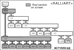
Disconnect C-122 SRS-ECU connector, and diagnose the CAN bus line.
|

|
OK: The display of the M.U.T.-III is as shown in the figure.
Q.
Does M.U.T.-III screen correspond to the illustration?
Repair the wiring harness between C-122 SRS-ECU connector and C-04 joint connector
(CAN1).
Check the SRS-ECU connector, and repair if necessary. If the SRS-ECU connector
is in good condition, replace the SRS-ECU.
|
|
|
STEP 41. M.U.T.-III CAN bus diagnostics (checking the A/C-ECU <vehicles
with A/C> or heater control unit <vehicles without A/C> for internal short)
|
|
|
| caution |
Strictly observe the specified wiring harness repair procedure.
For details refer to .
|
|
|
|
Disconnect C-15 A/C-ECU connector <vehicles with A/C> or C-60 heater control
unit connector <vehicles without A/C> , and diagnose the CAN bus line.
|
|
OK: The display of the M.U.T.-III is as shown in the figure.
Q.
Does M.U.T.-III screen correspond to the illustration?
Repair the wiring harness between C-15 A/C-ECU connector <vehicles
with A/C> or C-60 heater control unit connector <vehicles without A/C> and C-04 joint connector
(CAN1).
Check the A/C-ECU connector <vehicles with A/C> or heater control
unit connector <vehicles without A/C>, and repair if necessary. If the A/C-ECU
connector <vehicles with A/C> or heater control unit connector <vehicles without A/C> is
in good condition, replace the A/C-ECU <vehicles with A/C> or heater control unit
connector <vehicles without A/C>.
|
|
|
STEP 42. M.U.T.-III CAN bus diagnostics (checking the WCM for internal
short)
|
|
|
| caution |
Strictly observe the specified wiring harness repair procedure.
For details refer to .
|
|
|
|
Disconnect C-06 WCM connector, and diagnose the CAN bus line.
|
|
OK: The display of the M.U.T.-III is as shown in the figure.
Q.
Does M.U.T.-III screen correspond to the illustration?
Repair the wiring harness between C-06 WCM connector and C-04 joint connector
(CAN1).
Check the WCM connector, and repair if necessary. If the WCM connector is in good
condition, replace the WCM.
|
|
|
STEP 43. M.U.T.-III CAN bus diagnostics (checking the KOS-ECU for
internal short)
|
|
|
| caution |
Strictly observe the specified wiring harness repair procedure.
For details refer to .
|
|
|
|
Disconnect C-23 KOS-ECU connector, and diagnose the CAN bus line.
|
|
OK: The display of the M.U.T.-III is as shown in the figure.
Q.
Does M.U.T.-III screen correspond to the illustration?
Repair the wiring harness between C-23 KOS-ECU connector and C-04 joint connector
(CAN1).
Check the KOS-ECU connector, and repair if necessary. If the KOS-ECU connector
is in good condition, replace the KOS-ECU.
|
|
|
STEP 44. M.U.T.-III CAN bus diagnostics (checking the CAN box unit
for internal short)
|
|
|
| caution |
Strictly observe the specified wiring harness repair procedure.
For details refer to .
|
|
|
|
Disconnect C-54 CAN box unit connector, and diagnose the CAN bus line.
|
|
OK: The display of the M.U.T.-III is as shown in the figure.
Q.
Does M.U.T.-III screen correspond to the illustration?
Repair the wiring harness between C-54 CAN box unit connector and C-04 joint connector
(CAN1).
Check the CAN box unit connector, and repair if necessary. If the CAN box unit
connector is in good condition, replace the CAN box unit.
|
|
|
STEP 45. M.U.T.-III CAN bus diagnostics (checking the radio and CD
player for internal short)
|
|
|
| caution |
Strictly observe the specified wiring harness repair procedure.
For details refer to .
|
|
|
|
Disconnect C-103 radio and CD player connector, and diagnose the CAN bus line.
|
|
OK: The display of the M.U.T.-III is as shown in the figure.
Q.
Does M.U.T.-III screen correspond to the illustration?
Repair the wiring harness between C-103 radio and CD player connector and C-04
joint connector (CAN1).
Check the radio and CD player connector, and repair if necessary. If the radio
and CD player connector is in good condition, replace the radio and CD player.
|
|
|
STEP 46. M.U.T.-III CAN bus diagnostics (checking the hands free-ECU
for internal short)
|
|
|
| caution |
Strictly observe the specified wiring harness repair procedure.
For details refer to .
|
|
|
|
Disconnect C-41 hands free-ECU connector, and diagnose the CAN bus line.
|
|
OK: The display of the M.U.T.-III is as shown in the figure.
Q.
Does M.U.T.-III screen correspond to the illustration?
Repair the wiring harness between C-41 hands free-ECU connector and C-04 joint
connector (CAN1).
Check the hands free-ECU connector, and repair if necessary. If the hands free-ECU
connector is in good condition, replace the hands free-ECU.
|
|
|
STEP 47. M.U.T.-III CAN bus diagnostics (checking the combination
meter for internal short)
|
|
|
| caution |
Strictly observe the specified wiring harness repair procedure.
For details refer to .
|
|
|
|
Disconnect C-01 combination meter connector, and diagnose the CAN bus line.
|
|
OK: The display of the M.U.T.-III is as shown in the figure.
Q.
Does M.U.T.-III screen correspond to the illustration?
Repair the wiring harness between C-01 combination meter connector and C-04 joint
connector (CAN1).
Check the combination meter connector, and repair if necessary. If the combination
meter connector is in good condition, replace the combination meter.
|
|
|
STEP 48. Trouble symptom check
|
|
|
Diagnose the CAN bus line, and check that normal condition is displayed.
|
|
|
Q.
Is the check result normal?
|
|
|
The trouble can be an intermittent malfunction (Refer to GROUP 00 - How
to use Troubleshooting/inspection Service Points - How to Cope with Intermittent
Malfunction ).
|
|
|
|
|
|
Check the ETACS-ECU connector, and repair if necessary. If the ETACS-ECU connector
is in good condition, replace the ETACS-ECU.
|
|
|
|