|
|
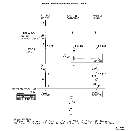
If the heater control unit is not energised, the power supply or earth system to the ECU may be defective.
|
|
|
- Malfunction of heater control unit
- Wiring harness or connector failure
|
|
|
Check that the ETACS-ECU has not set a diagnosis code.
|
|
|
Q.
Is the diagnosis code set?
|
|
|
 Carry out the diagnosis code procedures . Refer to GROUP 54A, ETACS-ECU Carry out the diagnosis code procedures . Refer to GROUP 54A, ETACS-ECU  . .
|
|
|
|
|
|
Q.
Is the check result normal?
|
|
|
 Repair the connector concerned. Repair the connector concerned.
|
|
|
|
|
|
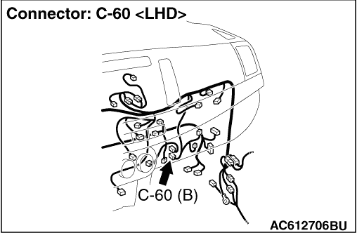
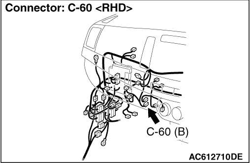
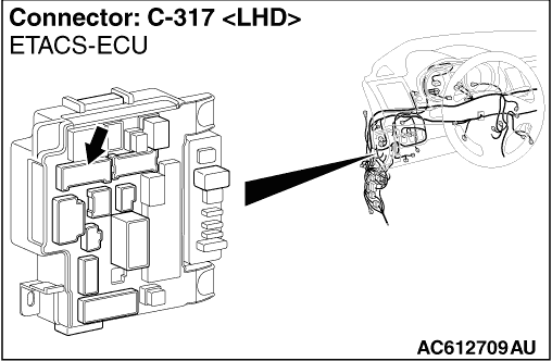
(1)Disconnect the connector, and measure at the wiring harness side.
|
|
|
(3)Voltage between terminal No. 15 and body earth
OK: System voltage
|
|
|
Q.
Is the check result normal?
|
|
|
Q.
Is the check result normal?
|
|
|
Repair the connector concerned.
|
|
|
|
|
|
- Check the power supply line for open circuit.
|
|
|
Q.
Is the check result normal?
|
|
|
Intermittent malfunction (Refer to GROUP 00 - How to Use Troubleshooting/Inspection Service Points - How to Cope with Intermittent Malfunction ).
|
|
|
|
|
|
Repair the wiring harness.
|
|
|
|
|
|
(1)Disconnect the connector, and measure at the wiring harness side.
|
|
|
(2)Voltage between terminal No. 13 and body earth
OK: System voltage
|
|
|
Q.
Is the check result normal?
|
|
|
- Check the power supply line for open circuit.
|
|
|
Q.
Is the check result normal?
|
|
|
Intermittent malfunction (Refer to GROUP 00 - How to Use Troubleshooting/Inspection Service Points - How to Cope with Intermittent Malfunction ).
|
|
|
|
|
|
Repair the wiring harness.
|
|
|
|
|
|
(1)Disconnect the connector, and measure at the wiring harness side.
|
|
|
(2)Resistance between terminal No. 14 and body earth
OK: Continuity exists (2 Ω or less)
|
|
|
Q.
Is the check result normal?
|
|
|
- Check the earth wires for open circuit.
|
|
|
Q.
Is the check result normal?
|
|
|
Intermittent malfunction (Refer to GROUP 00 - How to Use Troubleshooting/Inspection Service Points - How to Cope with Intermittent Malfunction ).
|
|
|
|
|
|
Repair the wiring harness.
|
|
|
|